0 installation, 1 unpacking and assembly, 2 enclosure disassembly – Rice Lake Survivor 390HE Hostile Environment Digital Indicator User Manual
Page 8: 3 cable connections, 1 load cells, Caution
4
SURVIVOR 390HE Installation Manual
2.0
Installation
This section describes procedures for connecting load
cell and serial communications cables to the 390HE
indicator. Assembly drawings and parts lists are
included for the service technician.
•
Use a wrist strap to ground yourself and protect
components from electrostatic discharge (ESD) when
working inside the indicator enclosure.
•
This unit uses double pole/neutral fusing which could
create an electric shock hazard. Procedures requiring
work inside the indicator must be performed by
qualified service personnel only.
•
The supply cord serves as the power disconnect for the
390HE. The power outlet supplying the indicator must
be installed near the unit and be easily accessible
2.1
Unpacking and Assembly
Immediately after unpacking, visually inspect the
390HE to ensure all components are included and
undamaged. The shipping carton should contain the
indicator, this manual, and a parts kit. If any parts
were damaged in shipment, notify Rice Lake
Weighing Systems and the shipper immediately.
The parts kit contains the items listed below:
•
Identification label.
•
Capacity and identification labels.
Identification label (PN 49958) includes
replacement overlay decals for indicators
using units other than pounds and kilograms.
•
3-position (PN 15888) and 7-position (PN
23165) pluggable terminal blocks for load cell
and serial communications connectors.
2.2
Enclosure Disassembly
The indicator enclosure must be opened to connect
load cell and communications cables. Power-off the
indicator and remove the screws that secure the
enclosure cover. Open the cover; the CPU/display
board is mounted to the enclosure cover.
2.3
Cable Connections
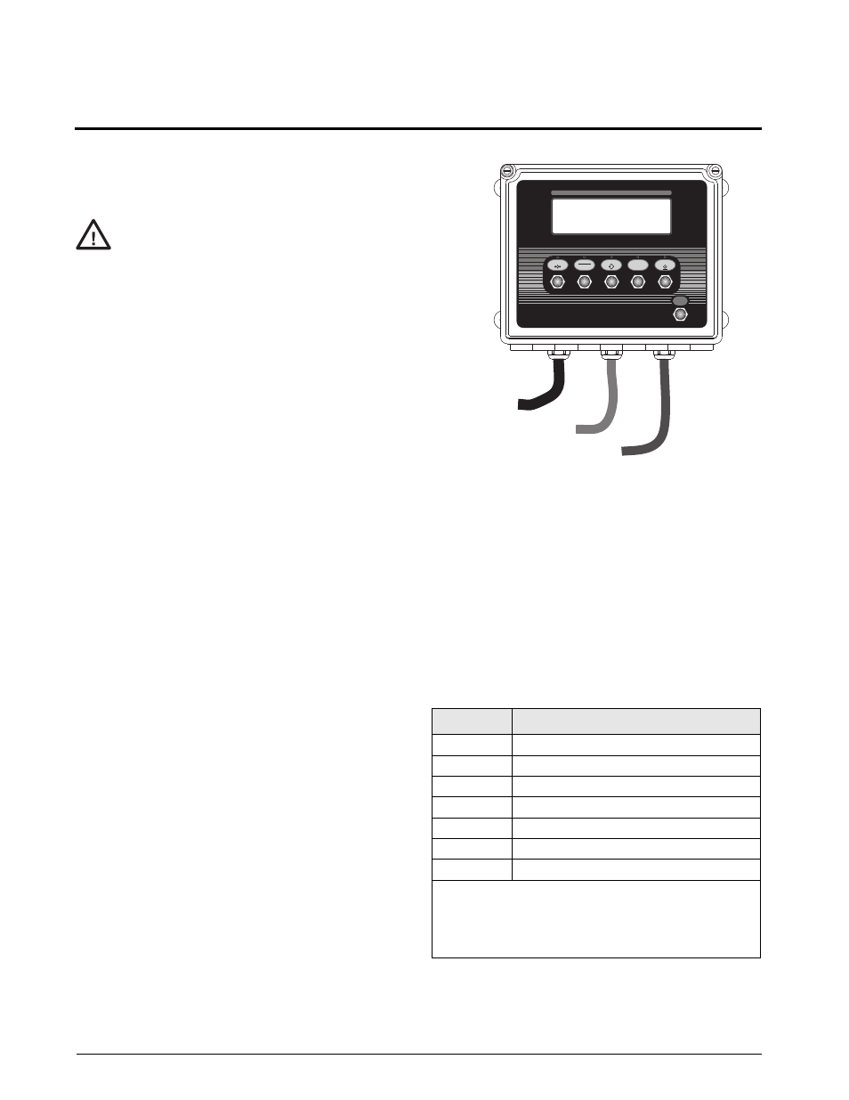
The 390HE provides three cord grips for cabling into
the indicator: one each for the load cell cable, serial
communications, and the AC power cord.
Figure 2-1. 390HE Cord Grip Assignments
2.3.1
Load Cells
To attach cable from a load cell or junction box,
remove connector J1 from the board. The connector
plugs into a header on the board. Connect cable from
the load cell or junction box through the load cell
cable cord grip to connector J1 as shown in Table 2-1.
If using 6-wire load cell cable (with sense wires),
remove jumpers JP1 and JP2 before reinstalling
connector J1 (see Figure 2-2). For 4-wire installation,
leave jumpers JP1 and JP2 on.
When connections are complete, reinstall connector J1
on the board.
Caution
J1 Pin
Function
1
+SIG
2
–SIG
3
+SENSE
4
–SENSE
5
SHIELD (nsee NOTE below)
6
+EXC
7
–EXC
NOTES:
• J1 SHIELD wire connection not used. Use ring terminal
to attach shield wire to grounded CPU board mounting
screw next to the J1 connector.
• For 6-wire connections, remove jumpers JP1 and JP2.
Table 2-1. J1 Pin Assignments
T
D I G I T A L W E I G H T I N D I C A T O R
MODE
ENTER
SAMPLE
I/O
ZERO
GROSS
NET
TARE
UNITS
T
B/G
Units
POWER
lb
kg
PC
AC Power
Serial Communications
Load Cell Cable