3 front panel configuration, Scribed in section 3.1.3, Normal mode key functions – Rice Lake Survivor 390HE Hostile Environment Digital Indicator User Manual
Page 13
Configuration
9
3.1.3
Front Panel Configuration
The 390HE indicator can be configured using a series of menus accessed through the indicator front panel when
the indicator is in setup mode. Table 3-1 summarizes the functions of each of the main menus.
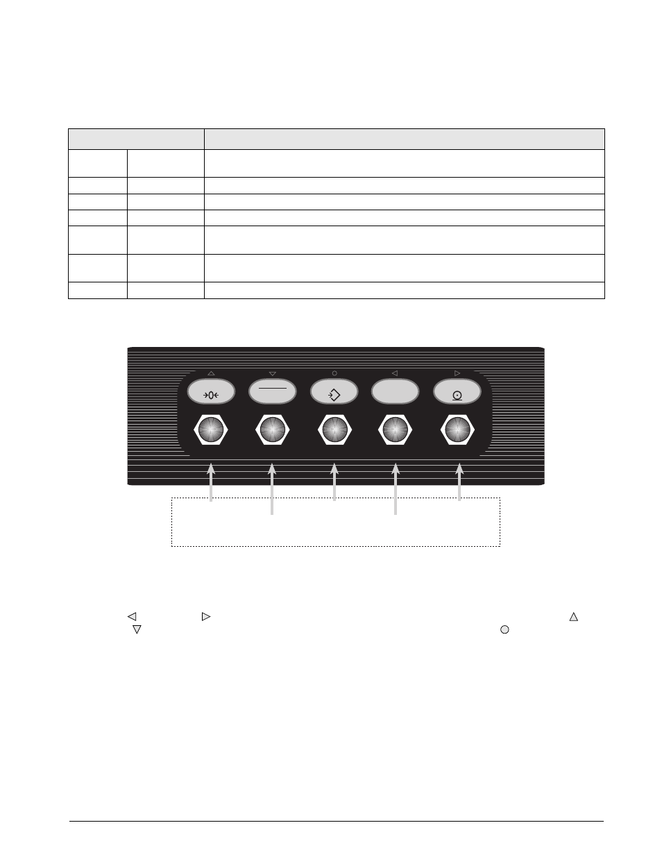
Figure 3-2. Front Panel Key Functions in Setup Mode
Four front panel keys are used as directional keys to navigate through the menus in setup mode (see Figure 3-2).
The
UNITS
( ) and
( ) keys scroll left and right (horizontally) on the same menu level;
ZERO
( ) and
GROSS/NET
( ) move up and down (vertically) to different menu levels. The
TARE
key ( ) serves as an Enter
key for selecting parameter values within the menus. A label over each of these keys identifies the direction
provided by the key when navigating through the setup menus.
Menu
Menu Function
CONFIG
Configuration
Configure grads, zero tracking, zero range, motion band, overload, tare function, and digital
filtering parameters.
FORMAT
Format
Set format of primary and secondary units, display rate.
CALIBR
Calibration
Calibrate indicator. See Section 4.0 on page 20 for calibration procedures.
SERIAL
Serial
Configure serial port.
PROGRM
Program
Set power-up and standby modes, counting scale functions, regulatory mode, unit ID and
consecutive number values.
P FORMT
Print Format
Set print format used for gross, net, and counting scale tickets. See Section 7.0 on page 27
for more information.
VERSION
Version
Display installed software version number.
Table 3-1. 390HE Menu Summary
Switch between
primary and
secondary units
Send data to
serial port
Set gross weight
to zero
Switch between
gross, net, and
piece count mode
Acquire tare
NORMAL MODE KEY FUNCTIONS
T
MODE
ENTER
SAMPLE
ZERO
GROSS
NET
TARE
UNITS
B/N
Units
T