3 electrical wiring and data connections, Power & alarm, socket is male – con 1 on pcb – Rice Lake OB-350 Loadrunner Series Onboard Weight Indicator User Manual
Page 9
Installation
5
3.3
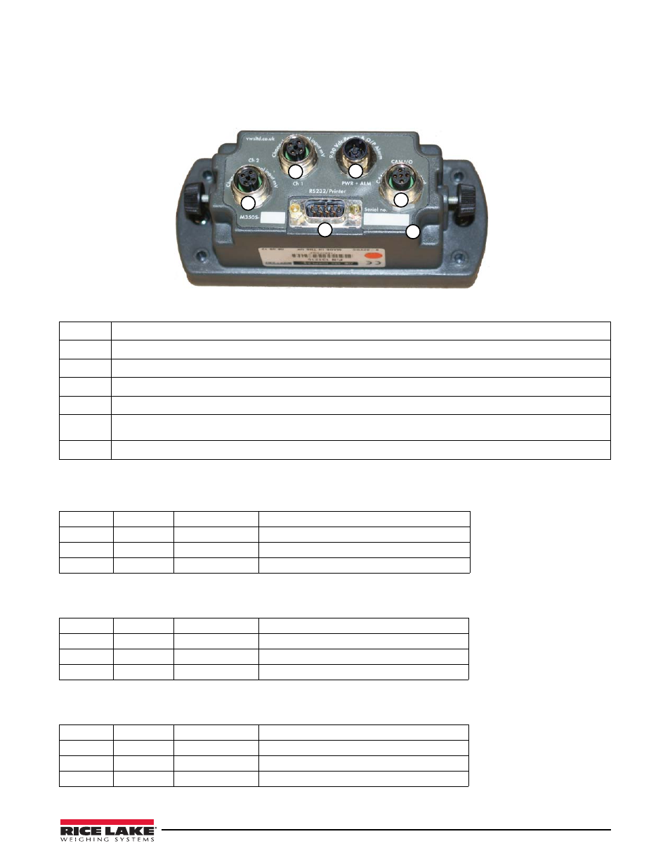
Electrical Wiring and Data Connections
The OB-350 is fitted with one Power and one Input Channel connector as standard. CANbus, Channel 2 and RS-232 are optional.
Full connector options is shown for illustration.
1
3
2
4
5
6
12B1D4FB
T
Figure 3-3. Rear Panel Identification and Bulkhead Connectors
Pin
Description
1
Input Channel 1, Max +/-39.0625 milli-Volts (also known as analog)
2
Input Channel 2, Max +/-39.0625 milli-Volts (also known as analog)
3
Power Input & Alarm Output
4
CANbus digital input & output
5
RS-232 output for printers and data capture devices (pin 9 = vehicle volts, pin 5 = ground, pin = 2 transmit, pin 3 =
receive)
6
Alpha-numeric unique indicator serial number, also appears on
power-on
SIGNAL channel 1 & 2, socket is FEMALE. – CON 2 & 3 on PCB
Pin 1
BROWN
+ Excitation
5 Volts DC
Pin 2
WHITE
+ Signal
milliVolts from the junction box & loadcells
Pin 3
BLUE
- Excitation
0 Volts
Pin 4
BLACK
- Signal
milliVolts from the junction box & loadcells
POWER & ALARM, socket is MALE – CON 1 on PCB
Pin 1
BROWN
Vehicle voltage
Supply 12V (LCV) or 24V (MCV & HGV)
Pin 2
WHITE
Output 1
12V or 24V
Pin 3
BLUE
Ground
Ground 0 Volts (common)
Pin 4
BLACK
Output 2
12V or 24V
CANbus input and output, plug is MALE – CON 5 on PCB
Pin 1
BROWN
+24V
+24 Volts DC Power Input
Pin 2
WHITE
GND
CAN bus LOW Output
Pin 3
BLUE
CANH
0 Volts Ground
Pin 4
BLACK
CANL
CAN bus HIGH Output