9 configuration menu – input, 1 input channel configuration – Rice Lake OB-350 Loadrunner Series Onboard Weight Indicator User Manual
Page 25
Technical Settings
21
6.9
Configuration Menu – Input
The Input Channel configuration determines what type of truck the
LoadRunner
system is being installed on. Use
the following settings and instructions for each type of truck used. Configuring the system differently will affect
how the unit performs. The input channel referenced also references the connection on the back of the indicator.
Roll Off/Dump Truck Configuration Settings
Parameter
Choices
Description
Input 1 (F)
Air/Oil Transducer
Air or Hydraulic Pressure Transducer
Input 1 (R)
Cell x 4
Load Cells
Split
Channel 2 fix
Straight Truck Configuration Settings
Parameter
Choices
Description
Input 1 (F)
Air/Oil Transducer
Air or Hydraulic Pressure Transducer
Input 1 (R)
Cell x 4
Load Cells
Split
Single Channel Cal
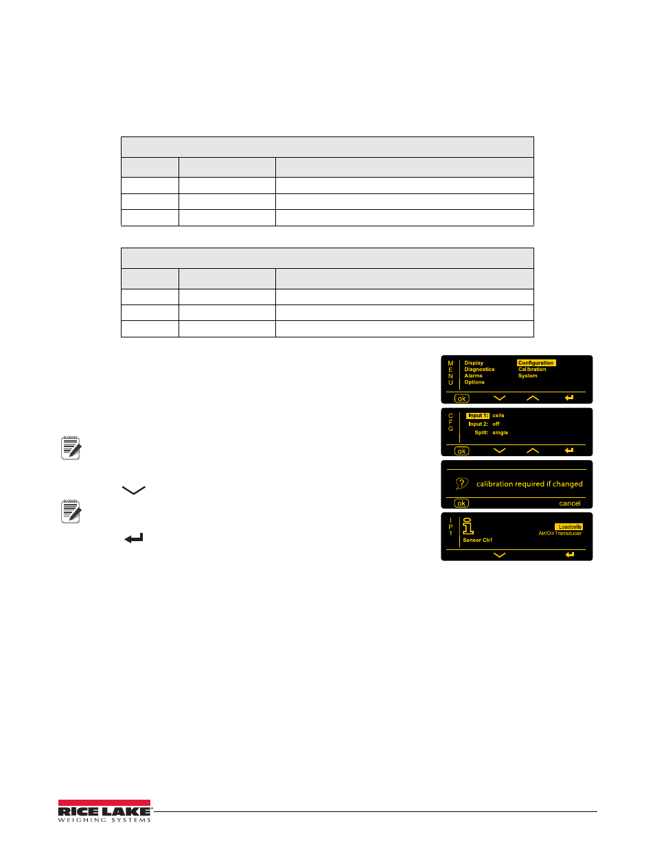
6.9.1
Input Channel Configuration
1. In MENU, select
Configuration
.
2. Press
(OK)
.
3. In CONFIGURATION, select
Input 1.
4. Press
(OK)
.
Input one is channel 1.
Note
5. Warning message appears, press
(OK)
to continue.
6.
Press
to select transducer type
.
Transducers are load cells, oil & air pressure sensors, etc.
Note
7. Press
to confirm setting.
8. If Input Channel 2 is connected, select
Input 2
and repeat 4-7.
Activating Input Channel 2 changes
Split
to
Dual
.
Definitions
• Input and Channel are used interchangeably.
• Transducers = load cells, oil & air pressure sensors, fifth-wheel load cells, etc.
• Split: single = One input channel, all transducers connected into one junction box (in parallel)
• Split: dual = Separate input channels, i.e. front and rear transducer sets are connected into the M350S
• Dual = Input channels 1 & 2 added together, the total weight of channel 1 & 2 will be displayed. Most VWS
load cells can be connected together in parallel as the milli-Volts signals are compatible. VWS load cells, oil
& air pressure transducers and fifth wheel load cells have different milli-Volt outputs and cannot be connected
into one junction box (with the exception of CANbus enabled sensors).
• Twin = Input channels 1 & 2 are displayed separately (e.g. the front and rear of a vehicle). Separate calibrations
are required which require weighing the front and rear axle/s separately and entering the data.