1 switching between modes, 1 converting to weigh mode, Converting to weigh mode – Rice Lake Mobile Group Animal Scale - MAS-M - Operators Manual User Manual
Page 24
20 MAS-M Operator’s Manual
3.1 Switching Between Modes
3.1.1 Converting to Weigh Mode
1. Park the scale in as level a location as possible. Ensure there are no obstructions
under the deck that would affect weighing accuracy.
The scale will weigh properly on a slope up to 4 degrees
(approximately 7%).
2. Turn the power switch located in the weigh center to the ON position.
3. If the scale is not level the indicator will display “
Out Of Level
” with the pitch
and roll angle below, allowing the scale to be leveled.
4. With the drop leg retracted extend the jack until it begins lifting up on the scale
hitch.
5. Disconnect the scale from the truck hitch and unplug all wiring. Move the truck
clear of the scale.
6. Using the hitch jack, lower the scale hitch to the ground.
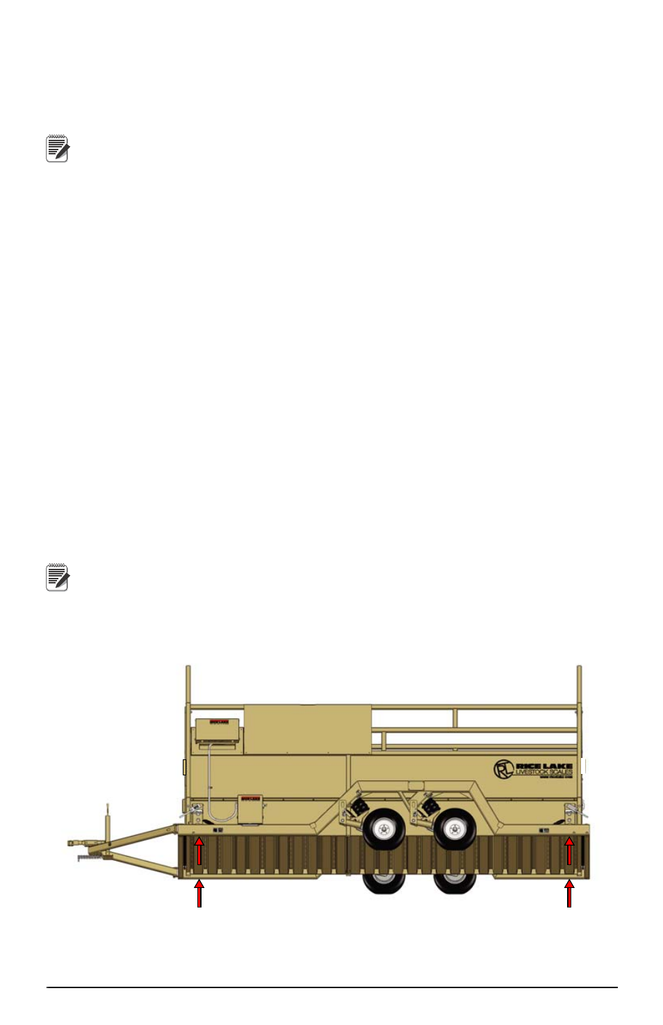
7. Flip the suspension stops (on each axle of the scale) into the weigh mode (see
Figure 3-3). Scale will not fully lower to ground with stops in transport
position.
8. Ensure the dump valve located on the battery box is closed and open all valves
located directly above the air bags.
9. Slowly open the dump valve to empty the air from the scale suspension. The
scale will lower to the ground.
10.Inspect all four corners of the scale. Although the scale will weigh properly up
to four degrees off level, individual corners of the scale should not be allowed to
teeter. If any of the corners are not contacting the ground, either move the scale
to a more level location or do the following:
11.Close the dump valve and turn on the air pump to slightly raise the scale. Once
the scale frame has lifted sufficiently, turn off the pump.
If the air pump is not functioning, the scale can be raised using the
auxiliary fill directly below the dump valve.
12.Place shims directly under the base frame, under the load cell stands, to prevent
teetering (see Figure 3-4).
13.Open the dump valves to lower the scale onto the ground and shims.
Figure 3-4. Shimming Locations
Note
Note