0 installation, 1 unpacking and assembly, 2 enclosure and connectors – Rice Lake 120 Digital Weight Indicator User Manual
Page 9: 1 serial communications, Installation, Serial communications
Installation
5
2.0
Installation
This section provides information for connecting load cell and serial communications cables to the 120 indicator.
2.1
Unpacking and Assembly
Immediately after unpacking, visually inspect the 120 to ensure all components are included and undamaged.
The shipping carton should contain the indicator with attached tilt stand, this manual, and a parts kit. If any parts
were damaged in shipment, notify Rice Lake Weighing Systems and the shipper immediately.
The parts kit contains the items listed below:
•
Capacity and identification labels
•
Load cell connector (PN 82505)
•
9V power supply adapter (PN 78611 for 115 VAC units, PN 78612 for 230 VAC units)
2.2
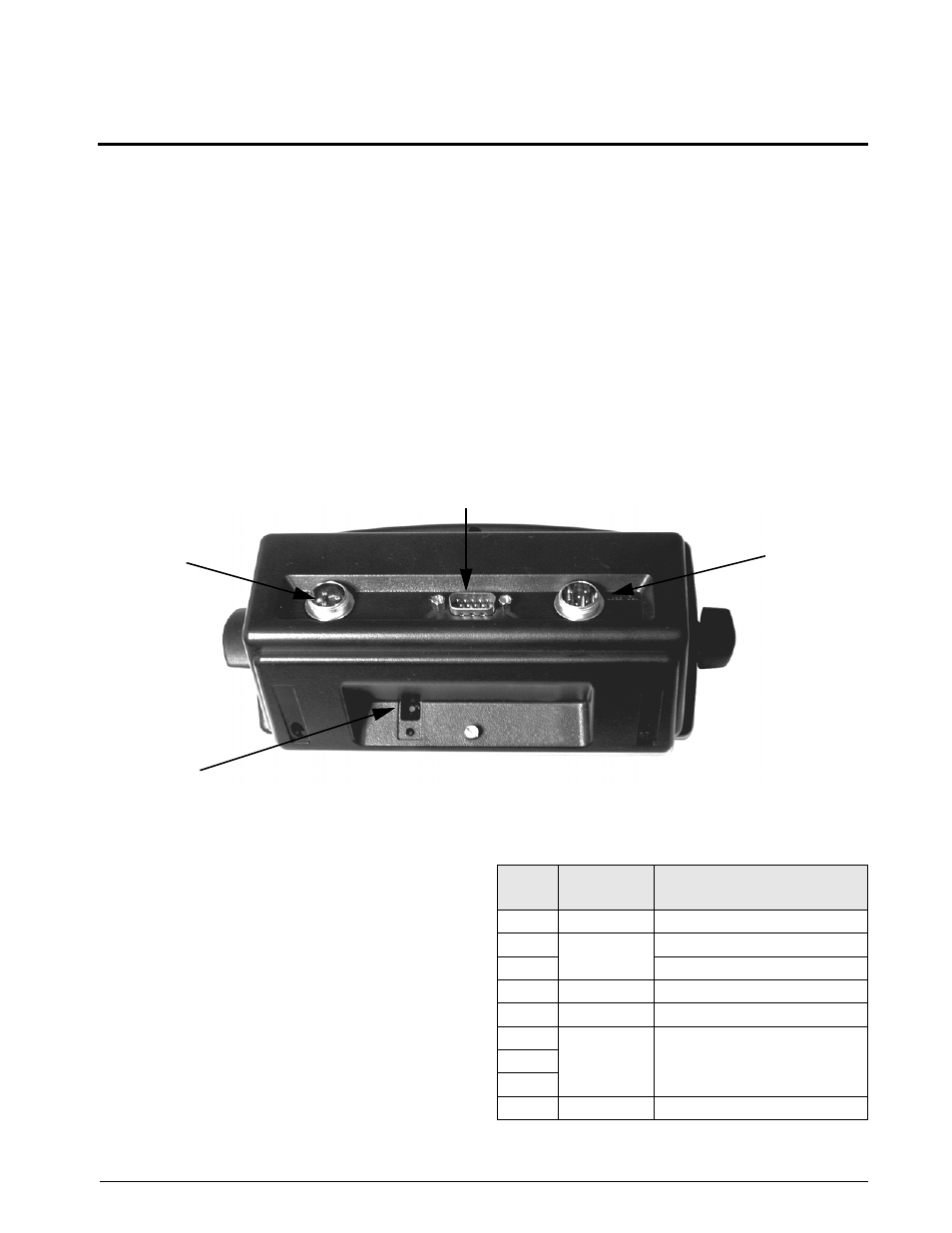
Enclosure and Connectors
The back of the 120 enclosure provides a 3-pin power connection, 9-pin D-sub connector for communications,
and an available 6-pin connector or load cell cord grip connector for load cell connection (see Figure 2-1).
The setup switch, used for placing the indicator into configuration mode, is located in the recess on the underside
of the enclosure. The setup switch is protected by a cover plate and secured with a fillister head screw (not shown
in Figure 2-1).
SETUP
PORT 1
PORT 2
COMMUNICATIONS
LOAD CELL
9VDC ADAPTER
SWITCH
D B - 9
Connecto
r
L o a d C e l l
Connect ion
s h o w n w it h
6 - p i n
C o n n e c t o r
(Port 2)
L o a d C e l l
C o r d G r i p
Available
Communications Port 1
Setup Switch
Figure 2-1. Back View of
120
Enclosure, Showing Load Cell DB-9 Connector, Communications Connectors and Setup
Switch Location
2.2.1
Serial Communications
The serial communications cable attaches to the male
D-Sub connector, Port 1 (see Figure 2-1 on page 5).
Port 1 provides connections for the EDP (Electronic
Data Processing) port and the printer port. Table 2-1.
shows the pin assignments for Port 1.
The EDP port supports RS-232 communications only;
the printer port provides either active 20 mA output or
RS-232 transmission. Both ports are configured using
the SERIAL menu. See Section 3.0 on page 7 for
configuration information.
Table 2-1. Serial Connector (Port 1) Pin Assignments
Port 1
Pin
Port
Function
1
Printer
RS-232 TxD
2
EDP
RS-232 TxD
3
RS-232 RxD
4
—
not used
5
EDP/Printer
RS-232 Ground / –20 mA OUT
6
N/C
not used
7
8
9
Printer
+20 mA OUT