2 load cells, 3 enclosure disassembly, 4 replacement parts – Rice Lake 120 Digital Weight Indicator User Manual
Page 10: Load cells, 3 enclosure disassembly 2.4 replacement parts
6
120 Installation Manual
2.2.2
Load Cells
Load cell wires can be wired up one of two ways
depending upon which indicator model is purchased.
Refer to the 6-pin connector instructions or the load
cell cord grip plug instructions to connect to the load
cell wires.
6-Pin Connector
The load cell or junction box cable attaches to the
round 6-pin connector, Port 2 (see Figure 2-1 on
page 5). Table 2-2 shows the pin assignments for
Port 2.
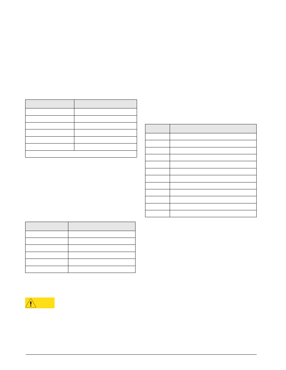
Table 2-2. Load Cell Connector (Port 2) Pin Assignments
Port 2 Pin
Function
1
+SIG
2
+EXC
3
+SENSE *
4
–EXC
5
–SENSE *
6
–SIG
* For 4-wire connections, short pin 2 to pin 3, pin 4 to pin 5.
Load Cell Cord Grip Plug
For models having the load cell cord grip, route cable
through the load cell cord grip and tighten the cord
grip. Next, remove connector J1 from the CPU board
which is located in the lower right side of the CPU
board. The connector plugs into a header on the board.
Wire the load cell cable from the load cell or junction
box to connector J1 as shown in Table 2-3.
Table 2-3. J1 Pin Assignments with Load Cell Cord Grip
J1
Function
1
–EXC
2
–SEN
3
–SIG
4
+SIG
5
+SEN
6
+EXC
2.3
Enclosure Disassembly
CAUTION
Use a wrist strap to ground yourself and
protect components from electrostatic
discharge (ESD) when working inside the
indicator enclosure.
If the indicator enclosure must be opened for
maintenance, do the following:
1. Disconnect power to the unit. Remove tilt stand.
2. Remove two fillister head screws and the setup
switch cover plate from back of enclosure.
3. Loosen self-tapping screw at top center of back
of enclosure.
4. Lift up the forward edge of the rubber feet on
bottom of enclosure for access to two additional
self-tapping screws. Loosen both screws.
5. Press down on top of back half of the enclosure
to release tabs. Open enclosure by separating the
housing at the top of the indicator. (CPU board
is mounted to front half of enclosure; power,
communications, and load cell connections all
connect to the bottom of the CPU board.)
6. Reverse steps to reassemble enclosure.
2.4
Replacement Parts
Table 2-4 lists replacement parts for the 120 indicator.
Table 2-4. Replacement Parts
PN
Description
78609
CPU Board
78610
Switch panel membrane
15799
9-pin socket for D-sub communications cable
15774
Shell for D-sub communications cable
83429
Setup switch cover plate
83430
Fillister head screw
83432
Self-tapping screw (enclosure)
83431
Rubber foot
83428
Tilt stand wing knob
78949
Optional wall-mount tilt stand
78611
9V power supply adapter for 115V units
78612
9V power supply adapter for 230V units