Understanding the cellpro 10s charger – ProgressiveRC 10S FMA Cellpro User Manual
Page 3
3
Understanding the Cellpro 10s Charger
You can set the Cellpro 10s Charger’s charge rate to one of three Auto modes—1C, 2C or
3C—as appropriate for the pack(s) being charged. When one of these rates is selected, the char-
ger determines the pack’s capacity and automatically sets the correct output current using FMA’s
advanced Fuel Gauging technology. You can also manually set charge current to any value
between 0.1A and 10A in 0.1A increments. Finally, you can select Storage Charge mode which
charges to 50% rated capacity using Fuel Gauging technology. The charger handles multiple
chemistries and charge parameter presets.
When one pack is connected to the charger, the pack is intially charged at the selected charge rate
(or the maximum charge rate possible). Using Ohm’s law, the maximum charge rate (Amps) is
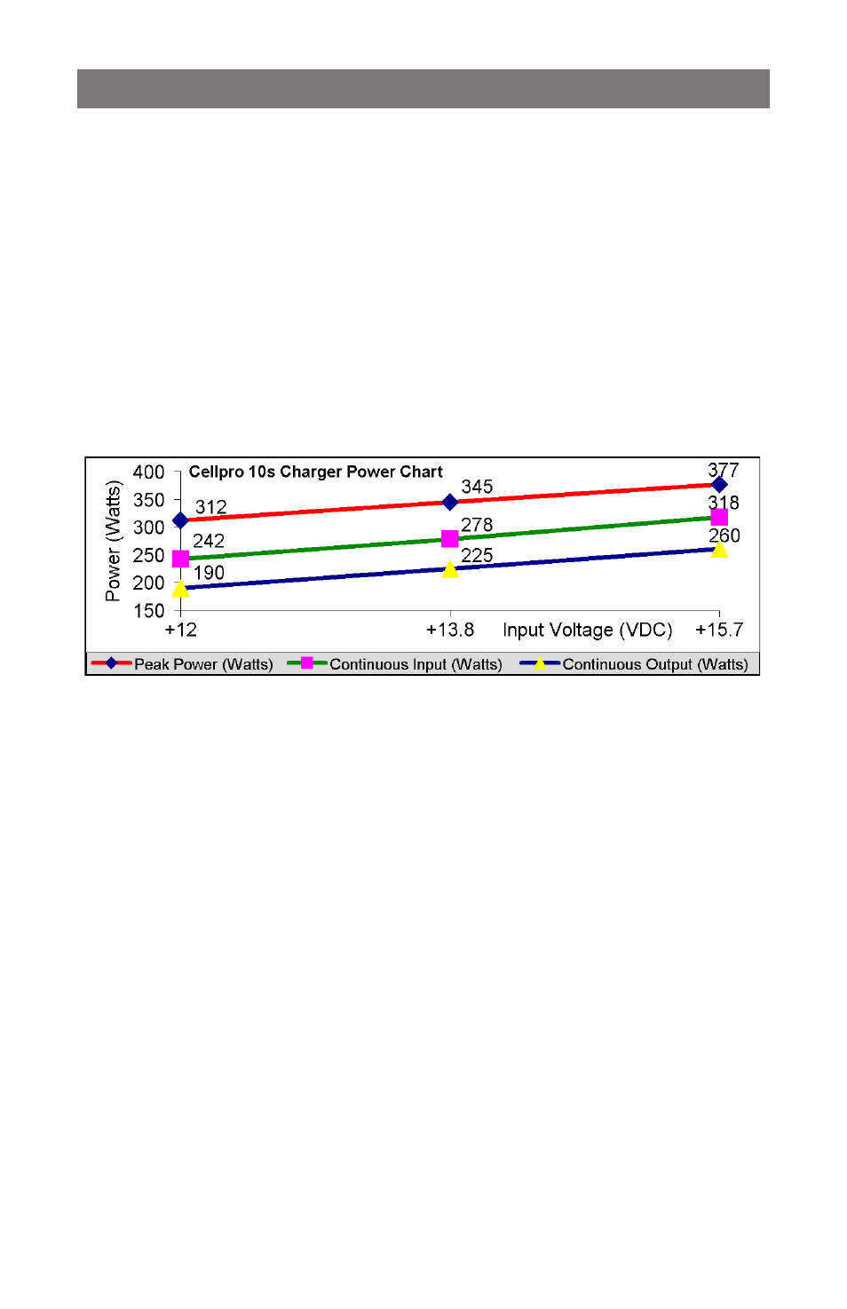
derived from the maximum power (Watts) the charger can produce without overheating.
Maximum power is approximately 300W measured at the charger input (FMA rates maximum
power using a 15V DC input source). Maximum power depends on many factors including pack
imbalance during charge, input (supply) voltage, output (charge) voltage, DC/DC converter ef-
ficiency (which varies between 80% and 90% depending on the relationship of supply voltage-to-
charge voltage), ambient temperature, and internal operating temperature.
Peak Power = Maximum input power charger draws for first 3-5 minutes of charge.
When the pack reaches about 90% capacity, the charger enters balance charge mode. Charge
current tapers off, but will remain at 1A or higher until the pack voltage slows the current to
1/20th C (Constant Voltage Mode). When the pack reaches 99% capacity, the charger beeps
three times. The pack can be removed to use, or allowed to continue charging until the pack is
100% full and the charger displays “Charge Complete.”
During the entire charge process, the charger power balances the pack using 1A current until
all cell voltages are within 1mV of each other. Power balancing is the process of beginning the
balancing process early in the charge cycle using high current to shunt excess cell voltage while
other cells in the pack have a chance to catch up. Power balancing means the pack tops off faster
and the total charge time is greatly reduced. This is possible because the balance circuitry is in-
ternal to the charger. Automatic temperature control and an integral fan ensure the charger never
exceeds maximum safe operating temperature under any conditions. The result is faster, safer
charge times.
When charging two packs, the packs are connected in series using four electronic switches inside
the charger. In effect, the charger treats the two packs as a single pack. (For example, if you
connect a 3s pack and a 4s pack, the charger operates on them as one 7s pack.) If the pack ca-
pacities are different for the two packs connected, the charge rate should be selected based on the
lower capacity pack. Initially, the packs are charged at the selected charge rate (or the maximum
charge rate possible) until one pack becomes fully charged—however, the charger handles cell
balancing of the two packs completely independently. The second pack continues to be charged
at a minimum of 1A charge rate until it is full and balanced.
Notice that one of the packs in a simultaneously charged pair is always topped off at a minimum
rate of 1A (dictated by the maximum balance current available). If the packs have the same ca-
pacity, and were discharged to about the same level, both packs will charge in less than 30 min-