Figure 11: hub and processor node port mapping, Figure 11 – Kontron SYMKLOUD MS2900 Web User Manual
Page 19
19
www.kontron.com
Quick Start Guide
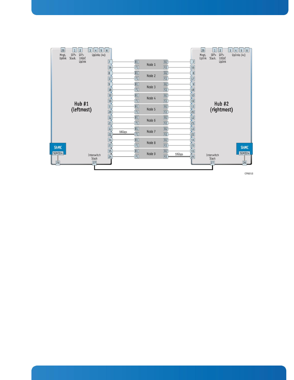
Figure 11: Hub and Processor Node Port Mapping
On both Hub 1 and Hub 2, port 2, labeled ’’2’’ on the hub faceplate, is the 10GbE uplink port. This is the port
that connects to the switch port #2.
On both Hub 1 and Hub 2, port 1, labeled ’’1’’ on the hub faceplate, is for stacking multiple SYMKLOUD
MS2900 systems. This port connects to switch port #1.
If the MS2900 system is equipped with optional rear uplink modules:
-
Stacking is performed using port 1 of each uplink module (marked on the faceplate), which is routed
to switch port #1.
-
A 10GbE uplink port is available on port 2 of each uplink module (marked on the faceplate) and
routed to switch port #2.
NOTE: In the SMBStaX™ GUI, port #1 is not visible since it is used for stacking.
Chassis slots 7 and 9 have 10GbE pipes to support up to two SYMbalance modules optionally or two additional
provisioning processor nodes:
-
Hub 1, port #22 (node 7 fabric 1)
-
Hub 2, port #24 (node 9 fabric 2)
All other ports are 1GbE.