Installation instructions – Kontron OmniView User Manual
Page 21
OmniView – User’s Guide (V1.)
20
www.kontron.com
7.
Installation Instructions
The OmniView should be installed and operated only by trained and qualified
personnel.
The unit must be placed such that there is sufficient space for connecting the cables
to the I/O interface connectors.
The voltage feeds must not be overloaded. Adjust the cabling and the external
overload protection to correspond with the rated voltage range indicated on the
type label.
The type label is located on the right side of the system.
The rear access panel must be secured by the supplied screws during operation.
The mount clamps with screws (supplied), allow the easy and fast mounting of the OmniView-
156/185/215. Refer to the appropriate unit outline and mounting drawing for the correct
dimensions of cut-outs and air gap clearances required for mounting the unit into a wall or panel.
The OmniView outline and mounting drawing can be found on our web sit
Dimension for: OmniClient
156
185
215
Cut-Out for Mounting into a Panel
[mm] (W x H)
394 x 245
462 x 283
527 x 325
Requirements for Mounting
Metal mounting panel thickness
for proper mounting
1.5 – 6
1.5 – 6
1.5 – 9
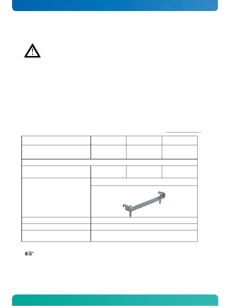
Used clamps with screws for
mounting the OmniClient to
a panel
6x
Required Tool
#2 Phillips Screw Driver
Proper Torque
Tighten the screws with a torque of 0.5 Nm
Mounting Position
Ensure the vertical and horizontal alignment of the
system/display box.
Table 2: Requirements for OmniView mounting into a subframe/panel
In order to ensure IP65 front sealing against dust and water, mount the system on a
non-textured surface. Before you install the OmniView system into a panel or a
subframe for industrial cabinet, verify the perfect condition of the seal at the rear of
the front plate. The seal has to be in place without surface imperfections/defects
and dirt.