Kontron SMARC Evaluation Carrier User Manual
Page 60
User’s Guide
60
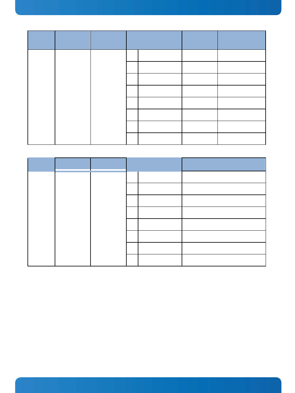
Part
Address (7 bit)
Address (8 bit)
I/O (Use as Output)
Default 1 R275
Out
Default 2 R275
In
U35
TI
TCA9554
0x22
0x44 / 0x45
P0
V_5V0_EN
Enabled
CARRIER_PWR_ON
P1
V_3V3_EN
Enabled
CARRIER_PWR_ON
P2
V_1V8_EN
Enabled
CARRIER_PWR_ON
P3
V_1V5_EN
Enabled
CARRIER_PWR_ON
P4
V_5V0_USB_EN
Enabled
CARRIER_PWR_ON
P5
V_3V3_PCIE_EN
Enabled
CARRIER_PWR_ON
P6
CAN0_1V8_EN
Enabled
CARRIER_PWR_ON
P7
CAN1_1V8_EN
Enabled
CARRIER_PWR_ON
Part
Address (7 bit)
Address (8 bit)
I/O (Use as Input)
Notes
U34
TI
TCA9554
0x24
0x48 / 0x49
P0
PG_5V0
Power Good – 5V rail
P1
PG_3V3
Power Good – 3.3V rail
P2
Not used
P3
PG_1V5
Power Good – 1.5V rail
P4
PG_5V0_USB
Power Good – 5V USB rail
P5
PG_3V3_PCIE
Power Good – 3.3V PCIe rail
P6
PG_SWITCHER
Power Good – Bat Step Down
P7
Not used
If resistor R275 is omitted, then the power rails shown above come on whenever the Evaluation Carrier has power. If
R275 is installed with a low value resistor, then the power rails are disabled until the Module asserts the
CARRIER_PWR_ON signal