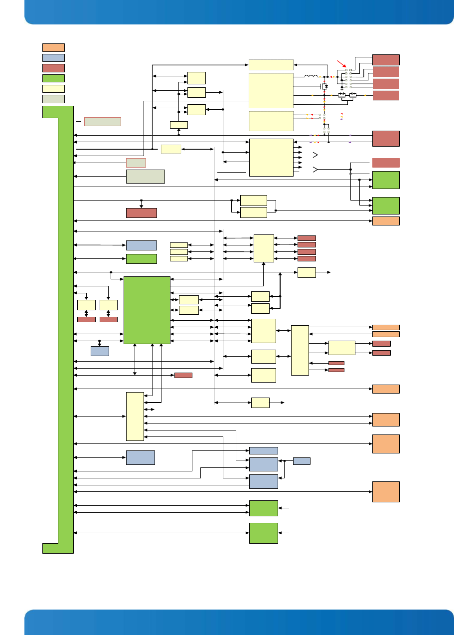
Figure 1. system block diagram – Kontron SMARC Evaluation Carrier User Manual
Page 12
User’s Guide
12
S
M
AR
C
C
ar
ri
er
C
onne
ct
or
:
314
P
in
0.
5m
m
P
it
ch
R
/A
MX
M3
S
ty
le
B
aseb
o
ar
d
C
onne
ct
or
Block Diagram Color Key:
Configuration Options
Industry standard connectors
for wired, off-board connections
Industry standard connectors
for mezzanine format connectors
Kontron defined connectors
Wired, off-board connections
Kontorn defined connectors
and mezzanines
IC and IC subsystems
Other features
RTC Backup
Power Source
(Batt / SuperCap)
I2C_PM
I2C_PM
I2C_PM
LDO
1.8V
I2C_PM
EEPROM
I2C
8 Bit I/O
TCA9554
I2C
8 Bit I/O
TCA9554
Enables
Status
Charge Status
Battery
Fuel Guage IC
BQ24171
Battery Charger
DC – DC
Converter
(Used only for 8.4V and 10.8V
Nominal Series Batteries)
(Depleted / Nominal / Fully Charged)
One level (3.0V / 3.6V / 4.2V)
Two level (6.0V / 7.2V / 8.4V)
Three level (9.0V / 10.8V / 12.6V)
Energy Flow Color Key:
Battery Energy
Charger Energy
Bench Supply Energy
Li-Ion
Battery
Li-Ion
Battery
Li-Ion
Battery
Charger
In
5V (single level cell)
12V (two level cell)
16V (three level cell)
Module Power (3.0V – 5.25V)
Power State Status Signals
I2C_PM
Charge Status
Boot Device elect
Jumper
Block
FET
Isolation
I2C_PM_CAR
Carrier
Power Supply
Enables
Carrier
Power Supply
Status
I2C_GP
Carrier Power
Supply Circuits
5V
3.3V
1.8V
1.5V
12V
LED
V_IN_MOD (3.0V – 5.25V)
V_IN_CAR (3.0V – 5.25V)
V_IO 1.8V Default
Allow build option for 3.3V
PWR
Test Bench
Power In
Header
Backlight Pwr
May be single 5V
Or single 3.3V
Or single 3.0V to 5.25V
Or dual supply in 3.0 to 5.25V
range
Used if separate
Backlight cable is
needed
Misc Ctrl (Pwr Btn etc)
Pwr Btn
Reset Btn
Force Recovery Btn
I2C_LCD
(variable, to 31.9V)
I2C_LCD
KLAS
LVDS
Connector
Mezzanine adapter
Add on KLAS card
has native LVDS panel
connector
LVDS
Module LVDS (Single Channel)
24 Bit Parallel LCD Data and Control
HDMI
Header
Parallel LCD Data
LVDS Xmitter
Odd Pixels
SN75LVDS83B
LVDS Xmitter
Even Pixels
SN75LVDS83B
Dual Ch 24 Bit LVDS
KLAS
LVDS
Connector
HDMI
Mezzanine adapter
Add on KLAS card
has native LVDS panel
connector
UARTs (2x 4 Wire and 2x 2 Wire)
SDIO (4 Bit)
SDIO / eMMC (8 Bit)
Micro SD Slot
eMMC Mezzanine
EEPROM
EEPROM
EEPROM
I2C_GP
I2C_CAM
I2C_LCD
SER3
SER2
SER1
SER0
RS232
XCVRS
2x
Texas Inst
TRS3253E
Header
Header
Header
Header
Enables
GPIO
CAN1
SER0 - 3
Carrier RS232
XCVR Disabled if
Port is used
on I/O Mezzanine
FETS
LED
s
(x12)
CAN0
CAN PHY
On-Semi
NCV7341
CAN PHY
On-Semi
NCV7341
I/O
MEZZANINE
100 pin Hirose FX8 Connector
Mux
Passthru /
Loopback
Mux
Passthru /
Loopback
I2S0
I2S1
I2S2
I2C_GP
I2C_GP
I2C
8 Bit I/O
TCA9554
I2C
8 Bit I/O
TCA9554
SMARC GPIO
May be read back
over I2C for test
Header
SPI1
SPI0
SPI
Header
I2C_PM_CAR
I2C_GP
I2C_CAM
I2C_LCD
I2C_PM_CAR
I2C_GP
I2C_CAM
I2C_LCD
Build Options
I2C_GP
Default
I2C
I2S
CODEC
Headphone
MIC
Dual Class D
Amplifiers
TRS Jack
TRS Jack
Header
EEPROM
(Socket)
I2C_GP, I2C_CAM, I2C_LCD
I2S0, I2S1, I2S2
I2S0
FSUSB43
Passthru /
Loopback/
Isolate
I2S
Wolfson
Micro
WM8903
Header
Line In
Header
SPDIF
Header
I2C_GP, I2C_LCD
(Build options)
Accelerometer
ST Micro
LIS302DL
Header Line Out
USB2
USB Type A
USB1
1:7
USB HUB
SMSC
USB2517
Not Used
I2C_GP
I2C
8 Bit I/O
TCA9554
Enables for subsystems
(I2S loopbacks,
RS232 XCVRs, etc)
USB
Type A
R/A Dual
USB0 (OTG )
SATA
PCIE_C
MO-300
SATA
PCIe x1 Slot
Mini PCIe
(PCIe / USB)
SIM
Card
USB
Micro AB
OTG
PCIE_B
PCIE_A
GBE
Mini PCIe
(PCIe / USB)
GBE
RJ45
With
Magnetics
CAM1 (CSI 4 pair / Parallel Low Order Bits)
CAM0 (CSI 2 pair / Parallel Hi Order Bits)
AFB
Camera
Mezzanine
AFB
Mezzanine
Connector
Support signals
Per SMARC spec
Support signals
Per SMARC spec
Figure 1. System Block Diagram