2 j23 - j25 battery connectors, 3 j28 charger input, 7 bench power supply – Kontron SMARC Evaluation Carrier User Manual
Page 24: J23 - j25 battery connectors, J28 charger input, Bench power supply
User’s Guide
24
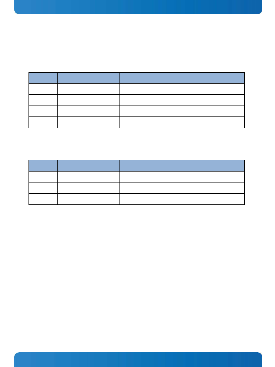
5.6.2 J23 - J25 Battery Connectors
J23, J24 and J25 are slots for inserting Battery 1, Battery 2 and Battery 3 respectively.
All the three connectors have the same pin-out.
Connector: TE-Connectivity 2-292173-6, 2mm pitch R/A SMT Header.
Pin Number
Signal
Notes
1,2
Battery Supply Positive
3
Battery Thermistor +
4
Battery Thermistor -
5,6
Battery Supply Negative
5.6.3 J28 Charger Input
Connector: Molex 39-30-3035
4.2mm pitch R/A through hole header
Pin Number
Signal
Notes
1
Charger Input
2
Ground
3
No Connect
Caution!
The charger voltage level depends on the battery configuration (single, dual or triple level cells – nominally
5V, 10V or 15V).
5.7
Bench Power Supply
The Evaluation Carrier may be powered by a lab bench supply over connector J29. This is the most common way that the
SMARC Evaluation Carrier is used.
There are two power feeds to the Bench Supply: one for the Evaluation Carrier circuits, and one for the Module. This
allows the Evaluation Carrier current and power consumption and the Module current and power consumption to be
measured separately. The two feeds may be combined and powered from a single source if the user does not care about
the separate measurements. The source(s) should be a DC supply in the 3.0 to 5.25V range.