Power supply, Atx mode / single supply mode, Table 14: atx mode – Kontron COMe-cPV2(v1.0) User Manual
Page 48
Kontron microETXexpress-PV User’s Guide
www.kontron.com
44
stated in the COM.0 specification, rather than the edge triggered SYS_RESET#
provided to the ICH.
This behavior is achieved through a combination of code running in
the CPLD and code in the BIOS. When
SYS_RESET# is kept asserted, a flag is also asserted in the CPLD. When the
BIOS starts, this flag is read and if it's found asserted, the BIOS enters
into a loop, thus preventing the board from booting. When the SYS_RESET# is
de-asserted, the CPLD will de-assert the flag and the BIOS will exit the loop
and issue a final platform reset.
Power Supply
The microETXexpress®-PV-XT COM has a wide range of power input, from 4.75V to
18V DC. The supply voltage is applied through 24 pins (VCC) on the module
connectors.
In general, single supply mode means that the module is able to function with
a single supply (no standby voltage is necessary). All other functions
attributed to the ATX mode remain functional.
WARNING: In ATX mode with 5V standby voltage, the VCC_12V input must be
higher than the standby voltage.
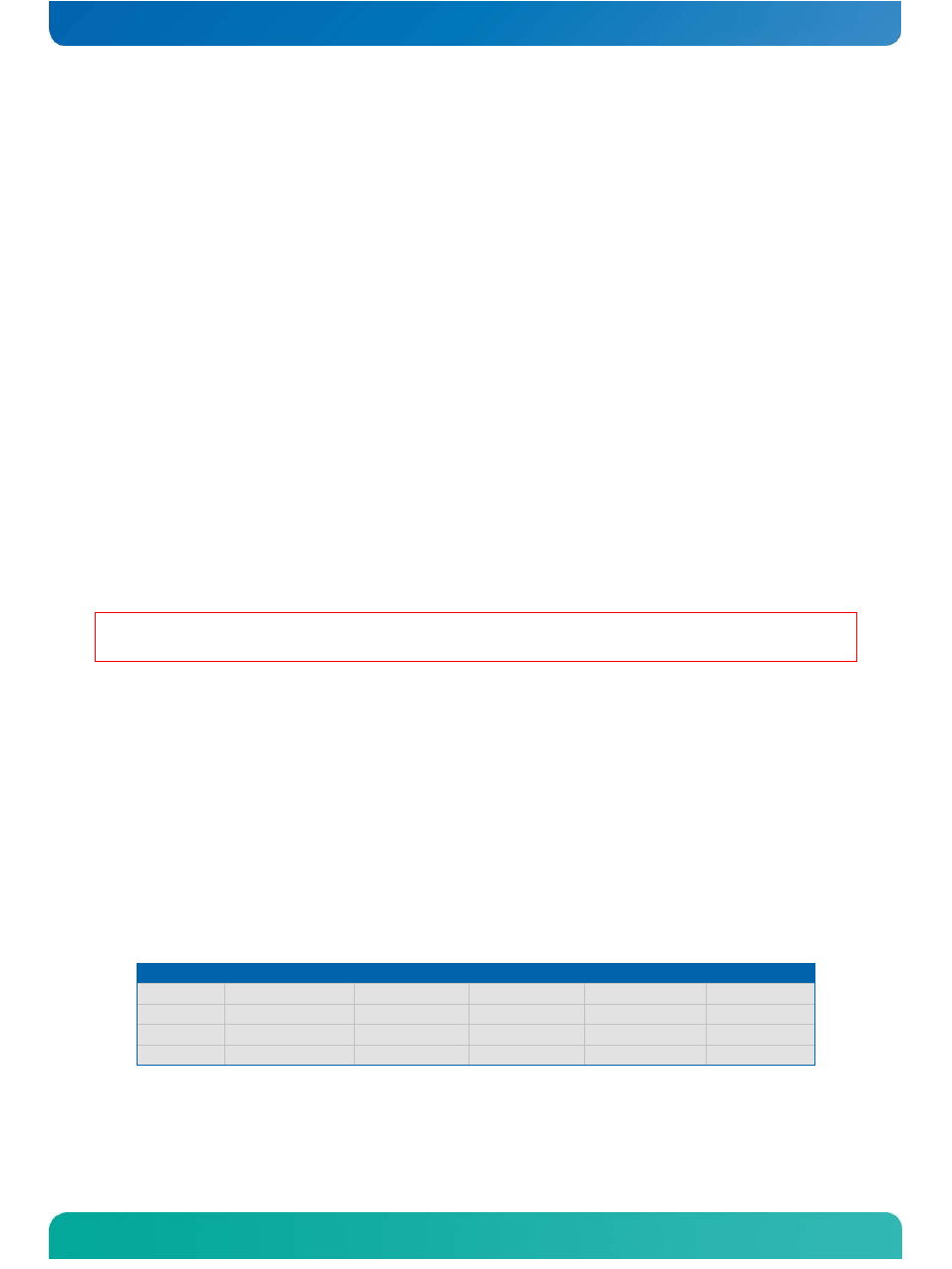
ATX Mode / Single Supply Mode
ATX Mode:
When an ATX power supply is connected, PWR_OK is set to low-level and VCC is
off. Pressing the power button enables the ATX PSU setting PWR_OK to high-
level and powers on VCC. The ATX PSU is controlled by the PS_ON# signal,
which is generated by SUS_S3# via inversion.
Table 14: ATX Mode
State
PWRBTN#
PWR_OK
V5_StdBy
PS_ON#
VCC
S3
x
x
5V
x
0V
S5
high
low
5V
high
0V
S5 -> S0
PWRBTN Event
low -> high
5V
high -> low
0 V-> VCC
S0
high
high
5V
low
VCC
Single Supply (Battery) Mode: