Sd-card interface (sdio), 4 sd-card interface (sdio), Onboard minisd/mmc socket j4 – Kontron COMe-cSP2 User Manual
Page 50: Sdio/gpio on com express® connector
COMe-cSP2
/ Special Features
45
5.4 SD-card Interface (SDIO)
The SD card standard is a standard for removable memory storages designed and licensed by the SD Card Association
(http://sdcard.org). The card form factor, electrical interface, and protocol are all part of the SD Card specification.
The Intel® US15W System Controller Hub supports up to 3 SDIO interfaces. On COMe-cSP2 the first interface SDIO#0 is
used for the onboard miniSD Card socket. The second Port SDIO#1 provides the SD card interface shared with the
module GPIO signals to the baseboard. SDIO#3 is not used and deactivated. The integrated SDIO 1.1 / MMC 4.1
controller in US15W SCH only supports byte-address mode for SDIO storage cards up to 2GB. Sector-addressing and
SDHC is not supported.
»
MMC 4.1 transfer rates can be up to 48MHz and bus widths of 1, 4 or 8 bits
»
SDIO 1.1 supports transfer rates up to 24MHz and bus widths of 1 or 4 bits
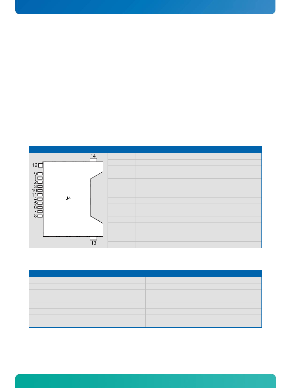
Onboard miniSD/MMC Socket J4
PIN
Description
1
DAT3/CD - Data Line 3/Card Detection
2
CMD - Command/Response
3
VSS 1 - Supply Voltage - GND
4
VDD - Supply Voltage - 3.3V
5
CLK - Clock
6
VSS2 - Supply Voltage - GND
7
DAT0 - Data Line 0
8
DAT1 - Data Line 1
9
DAT2 - Data Line 2
10
n.c.
11
n.c.
12
Detect
13
Ground 0
14
Ground 1
15
Ground 2
SDIO/GPIO on COM Express® Connector
General purpose Input/Output
SD card interface signals
GPI0
SLOT0_DATA0
GPI1
SLOT0_DATA1
GPI2
SLOT0_DATA2
GPI3
SLOT0_DATA3
GPO0
SLOT0_CLK
GPO1
SLOT0_CMD
GPO2
SLOT0_WP
GPO3
SLOT0_CD#