Lpc bus – Kontron COMe-cSP2 User Manual
Page 42
COMe-cSP2
/ COMe-cSP2 Connector
37
4.3.8 LPC Bus
The Low Pin Count (LPC) Interface signals are connected to the LPC Bus bridge, which is located in the Intel® US15W
system controller hub. The LPC low speed interface can be used for peripheral circuits such as an external Super I/O
Controller, which typically combines legacy-device support into a single IC. The implementation of this subsystem
complies with the COM Express® Specification. Implementation information is provided in the COM Express® Design
Guide maintained by PICMG. Please refer to the official PICMG documentation for additional information.
The LPC bus does not support DMA (Direct Memory Access). This leads to limitations for ISA bus and SIO (standard
I/O´s like Floppy or LPT interfaces) implementations. When more than one device is connected to the LPC bus a clock
buffer is required!
Warning: Due to the power management feature of the LPC Bus, clock buffers that require synchronization should be
used with great care and may prevent the board from booting up.
Active LPC Clock frequency
»
with Z530 CPU: 33MHz
»
with Z510 CPU: 25MHz
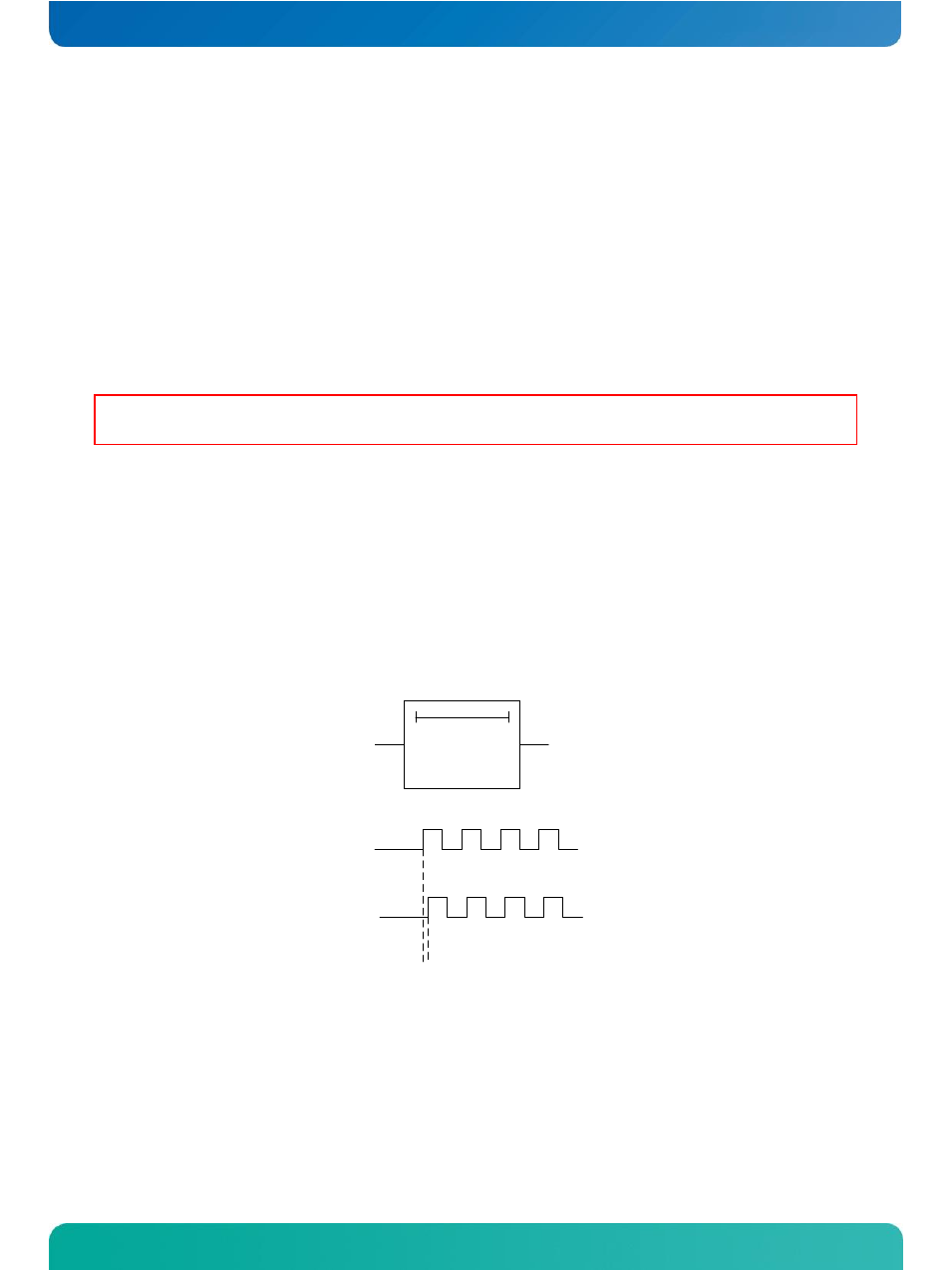
Standard Clock Buffer
Clk1
Clk2
TTL Buffer
Clk1
Clk2
...
...
When using a standard clock buffer on the baseboard please be aware that the generated delay has to be considered
for the length matching of the layout.
Clock Buffer Reference Schematic
The implementation of a clock buffer can be achieved as shown in the evaluation schematic below: