Kontron COMe-cSP2 User Manual
Page 32
COMe-cSP2
/ COMe-cSP2 Connector
27
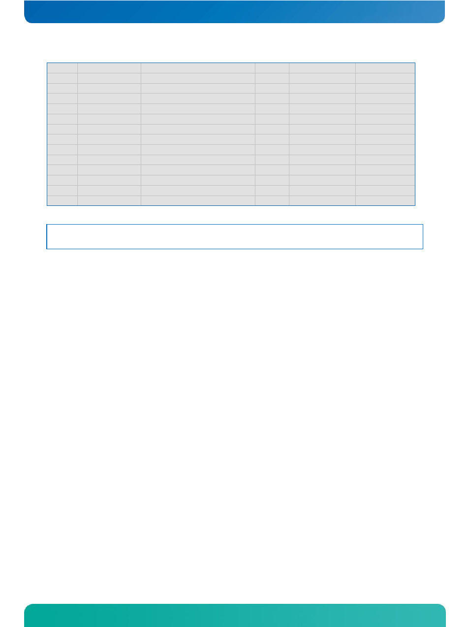
D97
PEG_ENABLE#
n.c.
Nc
-
-
D98
PEG_TX14+
n.c.
Nc
-
-
D99
PEG_TX14-
n.c.
Nc
-
-
D100
GND
Power Ground
PWR
-
-
D101
PEG_TX15+
n.c.
Nc
-
-
D102
PEG_TX15-
n.c.
Nc
-
-
D103
GND
Power Ground
PWR
-
-
D104
VCC_12V
12V VCC
PWR
-
-
D105
VCC_12V
12V VCC
PWR
-
-
D106
VCC_12V
12V VCC
PWR
-
-
D107
VCC_12V
12V VCC
PWR
-
-
D108
VCC_12V
12V VCC
PWR
-
-
D109
VCC_12V
12V VCC
PWR
-
-
D110
GND
Power Ground
PWR
-
-
Note:
The termination resistors in this table are already mounted on the COM Express® module. Refer to the COM
Express® design guide for information about additional termination resistors.
See also other documents in the category Kontron Hardware:
- CP3003-SA uEFI BIOS (72 pages)
- CP3003-SA (36 pages)
- CP3002 (38 pages)
- CP3002-RC uEFI (64 pages)
- CP-RIO3-05 (42 pages)
- CP3002-RC (30 pages)
- CP342 (52 pages)
- CP930 (46 pages)
- CP932 (52 pages)
- CP346 (72 pages)
- CP384 (66 pages)
- CP383 (74 pages)
- CP382 (58 pages)
- CP381 (60 pages)
- CP372 (64 pages)
- CP371 (60 pages)
- CP-RIO3-04S (38 pages)
- CP390 (36 pages)
- CPS3410 (9 pages)
- CPS3402 (9 pages)
- CPS3105 (9 pages)
- CPS3101 (9 pages)
- CPS3003-SA (19 pages)
- PB-SIO4 (34 pages)
- PB-SIO4A (34 pages)
- PB-DOUT8 (34 pages)
- VMOD-2 (82 pages)
- VSBC-32 (110 pages)
- VM42 (62 pages)
- Bootstrap Loader (24 pages)
- VMP1 with Netbootloader (120 pages)
- VMP1 (106 pages)
- NetBootLoader (86 pages)
- VMP2 (142 pages)
- VMP3 (154 pages)
- CP-RIO6-923 (32 pages)
- CP-RIO6-923-F (32 pages)
- CP-RIO6-001 (28 pages)
- CP-RIO6-001-HD-VGA (46 pages)
- CP-RIO6-M (20 pages)
- CP-RIO6-B (28 pages)
- CP6925 (42 pages)
- CP6002 uEFI BIOS (76 pages)
- CP6002 IPMI (40 pages)
- CP6002 (42 pages)