Kontron COMe-cSP2 User Manual
Page 26
COMe-cSP2
/ COMe-cSP2 Connector
21
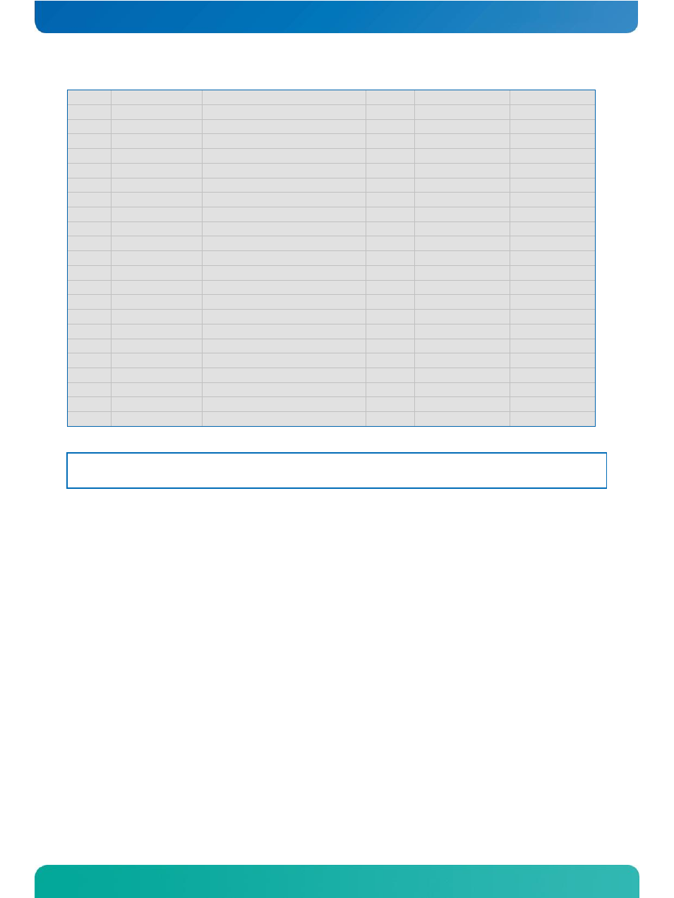
B88
RSVD5
Reserved
-
-
-
B89
VGA_RED
Not Connected
nc
-
not supported
B90
GND_25
Power Ground
PWR
-
-
B91
VGA_GRN
Not Connected
nc
-
not supported
B92
VGA_BLU
Not Connected
nc
-
not supported
B93
VGA_HSYNC
Not Connected
nc
-
not supported
B94
VGA_VSYNC
Not Connected
nc
-
not supported
B95
VGA_I2C_CK
Not Connected
nc
-
not supported
B96
VGA_I2C_DAT
Not Connected
nc
-
not supported
B97
TV_DAC_A
Not Connected
nc
-
not supported
B98
TV_DAC_B
Not Connected
nc
-
not supported
B99
TV_DAC_C
Not Connected
nc
-
not supported
B100
GND_26
Power Ground
PWR
-
-
B101
VCC_12V_13
12V VCC
PWR
-
-
B102
VCC_12V_14
12V VCC
PWR
-
-
B103
VCC_12V_15
12V VCC
PWR
-
-
B104
VCC_12V_16
12V VCC
PWR
-
-
B105
VCC_12V_17
12V VCC
PWR
-
-
B106
VCC_12V_18
12V VCC
PWR
-
-
B107
VCC_12V_19
12V VCC
PWR
-
-
B108
VCC_12V_20
12V VCC
PWR
-
-
B109
VCC_12V_21
12V VCC
PWR
-
-
B110
GND_27
Power Ground
PWR
Note:
The termination resistors in this table are already mounted on the COM Express® board. Refer to the design
guide for information about additional termination resistors.