4 io-area connectors, 1 display connectors (io area), 1 dvi connector (dvi-i) (j41) – Kontron KTHM65-mITX User Manual
Page 30: Io-area connectors, Display connectors (io area), Dvi connector (dvi-i) (j41)
KTHM65 Users Guide
KTD-N0838-A Page 30
4 IO-Area Connectors
4.1 Display connectors (IO Area)
The KTHM65 provides one on-board DVI-I port (both digital and analogue), two on-board DP’s
(DisplayPort) and one on-board LVDS panel interface. Two graphic pipes are supported; meaning that
up to two independent displays can be implemented using any two of the above mentioned graphic
ports.
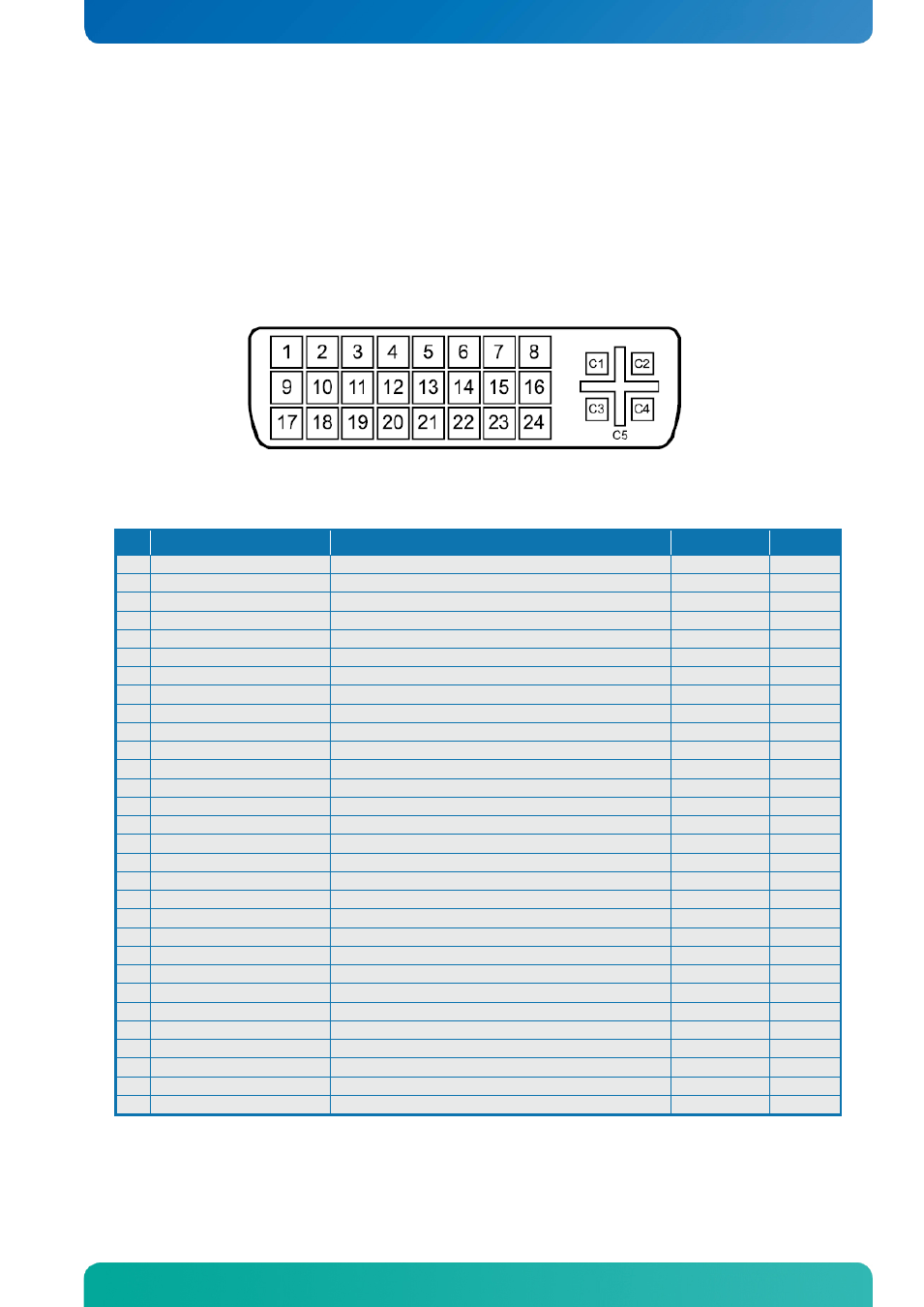
4.1.1 DVI Connector (DVI-I) (J41)
The
DVI-I connector support DVI Digital output and DVI Analogue output.
Female socket, front view
Signal Description - DVI Connector:
Pin
Signal
Description
Type
Pull U/D
1
TMDS Data 2-
Digital Red – (Link 1)
LVDS OUT
2
TMDS Data 2+
Digital Red + (Link 1)
LVDS OUT
3
TMDS Data 2/4 Shield
PWR
4
NC
NC
5
NC
NC
6
DDC Clock
DDC Clock
IO
2K2
7
DDC Data
DDC Data
IO
2K2
8
NC
NC
9
TMDS Data 1-
Digital Green – (Link 1)
LVDS OUT
10
TMDS Data 1+
Digital Green + (Link 1)
LVDS OUT
11 TMDS Data 1/3 Shield
PWR
12
NC
NC
13
NC
NC
14
+5V
Power for monitor when in standby
PWR
15
GND
PWR
16
Hot Plug Detect
Hot Plug Detect
I
17
TMDS Data 0-
Digital Blue – (Link 1) / Digital sync
LVDS OUT
18
TMDS Data 0+
Digital Blue + (Link 1) / Digital sync
LVDS OUT
19 TMDS Data 0/5 Shield
PWR
20
NC
NC
21
NC
NC
22
TMDS Clock Shield
PWR
23
TMDS Clock+
Digital clock + (Link 1)
LVDS OUT
24
TMDS Clock-
Digital clock - (Link 1)
LVDS OUT
C1
ANALOG RED
Analog output carrying the red color signal
O
/75R
C2
ANALOG GREEN
Analog output carrying the green color signal
O
/75R
C3
ANALOG BLUE
Analog output carrying the blue color signal
O
/75R
C4
ANALOG HSYNC
CRT horizontal synchronization output.
O
C5
ANALOG GND
Ground reference for RED, GREEN, and BLUE
PWR
C6
ANALOG GND
Ground reference for RED, GREEN, and BLUE
PWR
Note: The +5V supply is fused by a 1.1A resettable fuse
IO-Area Connectors