System specification – Kontron KTHM65-mITX User Manual
Page 11
KTHM65 Users Guide
KTD-N0838-A Page 11
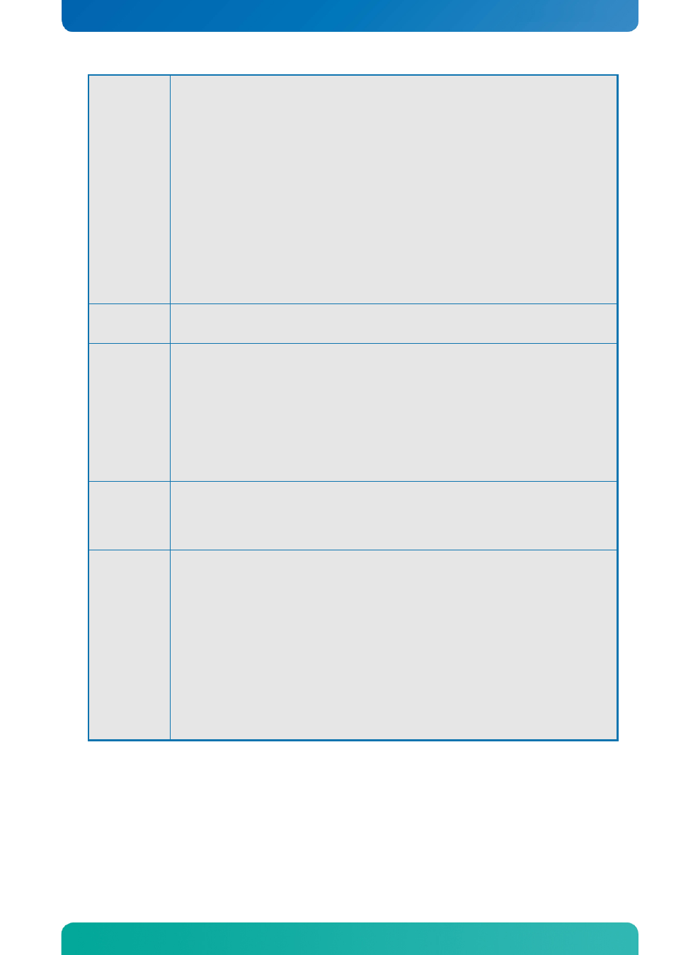
Video
Intel i3, i5 & i7 3
rd
Generation Mobile processors support Intel HD Graphics 4000.
(Note that triple independent pipes are not supported on HM65 chipset)
Intel i3, i5 & i7 2
nd
Generation Mobile processor supports Intel HD Graphics 3000.
Intel Celeron Processor B810 supports Intel HD Graphics.
Analogue VGA and digital display ports (DVI, 2x DP, LVDS) via the Mobile Intel ®
HM65 Chipset.
•
VGA (analogue panel) via DVI-I (sharing DVI-I connector with DVI-D)
•
DVI-D (sharing DVI-I connector with analogue VGA)
•
DP (DisplayPorts) dual, comply with DisplayPort 1.1a specification.
•
LVDS panel support up to 24 bit, 2 pixels/clock and 1920x1200.
•
HDMI panel support via DP to HDMI Adapter Converter.
•
Second VGA panel support via DP to VGA Adapter Converter
•
Second DVI panel support via DP to DVI Adapter Converter
•
Dual independent pipes for Mirror and Dual independent display support
I/O Control
Via ITE IT8516E Embedded Controller and Nuvoton W83627DHG I/O Controller (both
via LPC Bus interface)
Peripheral
interfaces
•
Six USB 2.0 ports on I/O area
•
Eight USB 2.0 ports on internal pinrows
•
Two IEEE 1394a-2000 (up to 400M bits/s) on internal pinrows
•
Four Serial ports (RS232) on internal pinrows
•
Two Serial ATA-600 IDE interfaces
•
Four Serial ATA-300 IDE interfaces
•
RAID 0/1/5/10 support
•
mSATA via mPCIe_0 connector
•
PS/2 keyboard and mouse ports via pinrow
LAN
Support
•
1x 10/100/1000Mbits/s LAN (ETHER1) using Intel® Lewisville 82579LM Gigabit
PHY connected to HM65 (AMT not supported)
•
PXE Netboot supported.
•
Wake On LAN (WOL) supported
Expansion
Capabilities
•
PCI-Express slot(s):
o 1 slot PCIex16 (PCIe 2.0) ( also PCIe 2.0 when using Ivy Bridge CPU)
o 1 slot PCIex1 (PCIe 2.0),
o 1 slot miniPCI-Express (PCI Express or mSATA signals, no USB signals)
o 1 slot miniPCI-Express (PCI Express signals, no mSATA or USB signals)
•
SMBus, compatible with ACCES BUS and I2C BUS, (via Feature connector)
•
SPI bus routed to SPI connector
•
DDC Bus routed to DVI-I connector
•
18 x GPIOs (General Purpose I/Os), (via Feature connector)
•
DAC, ADC, PWM and TIMER (Multiplexed), (via Feature connector)
•
WAKE UP / Interrupt Inputs (Multiplexed), (via Feature connector)
•
3 Wire Bus for GPIO Expansion (up to 152 GPIOs), (via Feature connector)
•
8 bit Timer output, (via Feature connector)
System Specification