11 ethernet connectors, 1 ethernet connector (lan), Ethernet connectors – Kontron KTUS15-mITX - 1.1 Basic User Manual
Page 36: Ethernet connector (lan)
KTD-00774-G
KTUS15/mITX
Page 36 of 84
4.11
Ethernet Connectors
The KTUS15 board support 1 channel of 10/100/1000Mb Ethernet using the Intel® 82574L PCI express LAN
controller.
In order to achieve the specified performance of the Ethernet port, Category 5 twistedpair cables must be
used with 10/100MB and Category 5E, 6 or 6E with 1Gb LAN networks.
The signals for the Ethernet ports are as follows:
Signal
Description
MDI[0]+ / MDI[0]-
In MDI mode, this is the first pair in 1000Base-T, i.e. the BI_DA+/- pair, and is the
transmit pair in 10Base-T and 100Base-TX.
In MDI crossover mode, this pair acts as the BI_DB+/- pair, and is the receive pair
in 10Base-T and 100Base-TX.
MDI[1]+ / MDI[1]-
In MDI mode, this is the second pair in 1000Base-T, i.e. the BI_DB+/- pair, and is
the receive pair in 10Base-T and 100Base-TX.
In MDI crossover mode, this pair acts as the BI_DA+/- pair, and is the transmit
pair in 10Base-T and 100Base-TX.
MDI[2]+ / MDI[2]-
In MDI mode, this is the third pair in 1000Base-T, i.e. the BI_DC+/- pair.
In MDI crossover mode, this pair acts as the BI_DD+/- pair.
MDI[3]+ / MDI[3]-
In MDI mode, this is the fourth pair in 1000Base-T, i.e. the BI_DD+/- pair.
In MDI crossover mode, this pair acts as the BI_DC+/- pair.
Note: MDI = Media Dependent Interface.
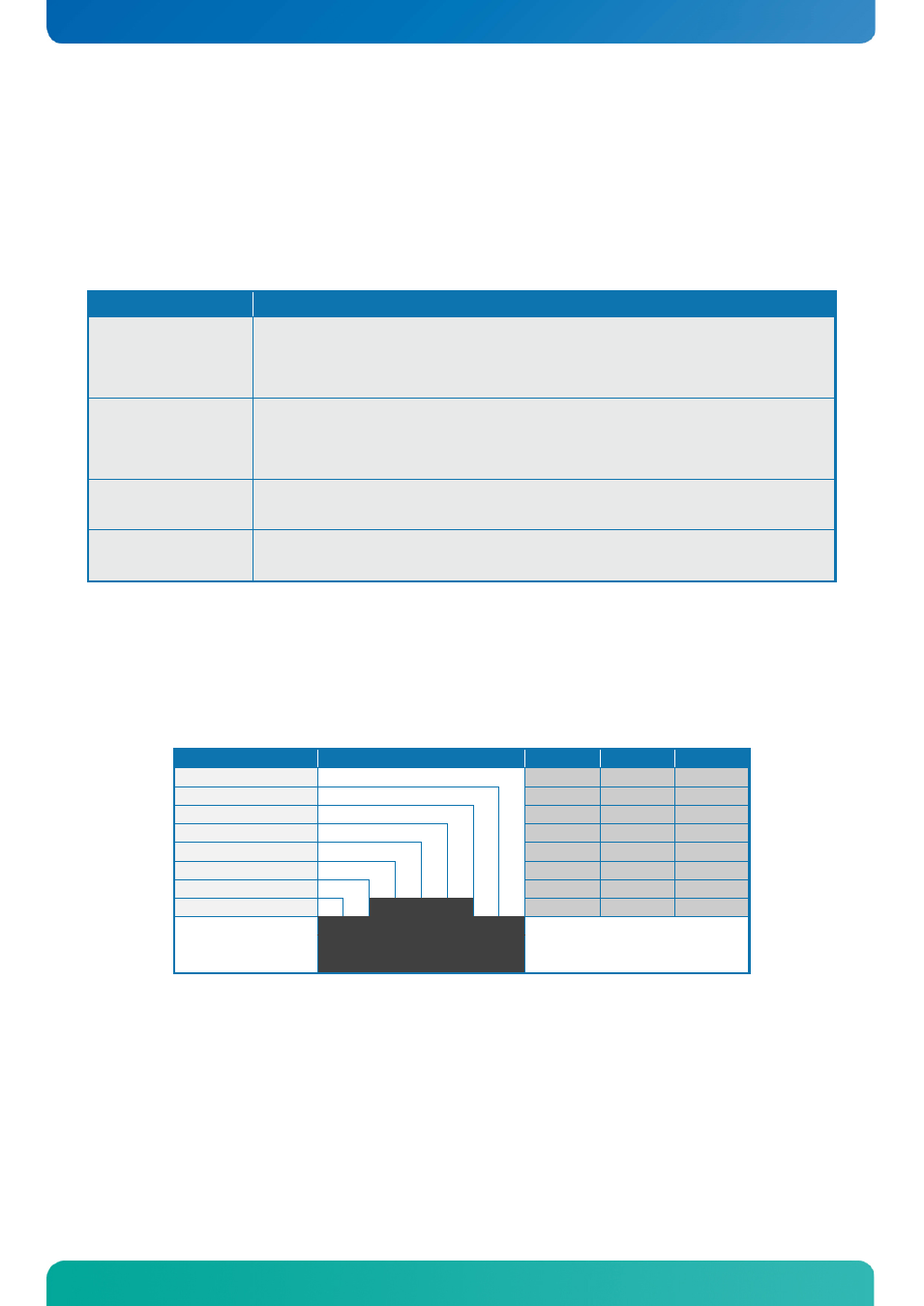
4.11.1
Ethernet Connector (LAN)
The pinout of the RJ45 connector is as follows:
Signal
PIN#
Type
Ioh/Iol
Note
MDI0+
MDI0-
MDI1+
MDI2+
MDI2-
MDI1-
MDI3+
MDI3-
8 7 6 5 4 3 2 1