1 connector layout, 1 ktus15/mitx – top side, Connector layout – Kontron KTUS15-mITX - 1.1 Basic User Manual
Page 21: Ktus15/mitx – top side
KTD-00774-G
KTUS15/mITX
Page 21 of 84
4.1
Connector layout
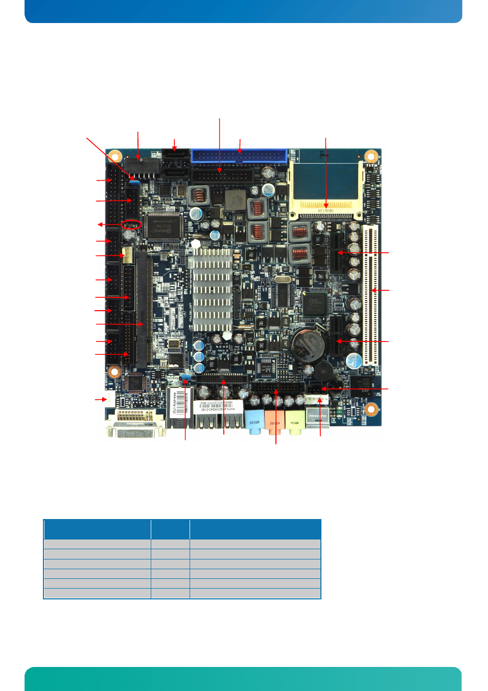
4.1.1 KTUS15/mITX – Top side
Status LED’s:
Colour combination
(D52 / D51/ D50)
Power
State
Notes
Green / Green / Green
S0
Running
Red / Green / Off
S3
Standby with RAM maintained
Red / Red / Off
S4/S5 Sleep
Yellow / Yellow / Don’t care
-
Failure if stuck in this combination.
Red / Yellow / Don’t care
-
Failure if stuck in this combination.
Yellow / Red / Don’t care
-
Failure if stuck in this combination.
Note: The color coding of the LED’s was different on EFT samples and first batches. The most significant
digit of the two digit “PCB ID” code (BIOS Main Menu) indicates the firmware version which is responsible for
the LED colors. This digit must be 4 (or above) otherwise don’t use the LED for anything.
Notes:
All connector except ”DDR2 SLOT”, “SDIO1” and “SDIO2” will be described in more details later in this chapter.
SATA1
SATA0
PWR
FRONTPNL
PATA
COMPACT FLASH
DDR2 SLOT
FAN CPU
COM3
TPM
Boot ROM
FEATURE
COM1
PRINTER
USB6/7
PWR-OUT
COM2
COM4
CDROM
Clr-CMOS
PCI Slot
KBDMSE
AUDIO-HEAD
PCIe x1 Slot 1
PCIe x1 Slot 2
LVDS
Status LED’s