3 lvds flat panel connector (lvds), Lvds flat panel connector (lvds) – Kontron KTUS15-mITX - 1.1 Basic User Manual
Page 28
KTD-00774-G
KTUS15/mITX
Page 28 of 84
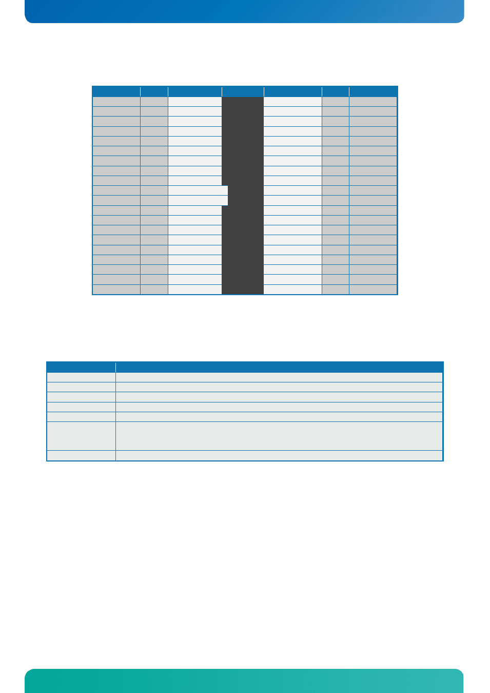
4.5.3 LVDS Flat Panel Connector (LVDS)
Note
Type
Signal
PIN
Signal
Type
Note
Max. 0.5A PWR
+12V
1 2
+12V
PWR Max. 0.5A
Max. 0.5A PWR
+12V
3 4
+12V
PWR Max. 0.5A
Max. 0.5A PWR
+12V
5 6
GND
PWR Max. 0.5A
Max. 0.5A PWR
+5V
7 8
GND
PWR Max. 0.5A
Max. 0.5A PWR
LCDVCC
9 10
LCDVCC
PWR Max. 0.5A
2K2Ω, 3.3V OT
DDC CLK
11 12
DDC DATA
OT 2K2Ω, 3.3V
3.3V level
OT
BKLTCTL
13 14
VDD ENABLE OT 3.3V level
3.3V level
OT
BKLTEN#
15 16
GND
PWR Max. 0.5A
LVDS LVDS A0-
17 18
LVDS A0+ LVDS
LVDS LVDS A1-
19 20
LVDS A1+ LVDS
LVDS LVDS A2-
21 22
LVDS A2+ LVDS
LVDS LVDS ACLK-
23 24
LVDS ACLK+ LVDS
LVDS LVDS A3-
25 26
LVDS A3+ LVDS
Max. 0.5A PWR
GND
27 28
GND
PWR Max. 0.5A
LVDS
N.C.
29 30
N.C.
LVDS
LVDS
N.C.
31 32
N.C.
LVDS
LVDS
N.C.
33 34
N.C.
LVDS
LVDS
N.C.
35 36
N.C.
LVDS
LVDS
N.C.
37 38
N.C.
LVDS
Max. 0.5A PWR
GND
39 40
GND
PWR Max. 0.5A
Note 1: The KTUS15 board supports single channel, 18/24bit OpenLDI/ SPWG panels on the LVDS
interface up to Wide XGA (1366x768 @ 85Hz) panel resolution. With an external 1-to-2 pixel per clock
converter, LVDS panels up to 1280x1024 are supported.
Signal Description – LVDS Flat Panel Connector:
Signal
Description
LVDS A0..A3
LVDS A Channel data
LVDS ACLK
LVDS A Channel clock
BKLTCTL
Backlight control (1), PWM signal to implement voltage in the range 0-3.3V
BKLTEN#
Backlight Enable signal (active low) (2)
VDD ENABLE Output Display Enable.
LCDVCC
VCC supply to the flat panel. This supply includes power-on/off sequencing.
The flat panel supply may be either 5V DC or 3.3V DC depending on the CMOS
configuration. Maximum load is 1A at both voltages.
DDC CLK
DDC Channel Clock
Note 1: Windows API will be available to operate the BKLTCTL signal. Some Inverters have a limited voltage
range 0- 2.5V for this signal: If voltage is > 2.5V the Inverter might latch up. Some Inverters
generates noise on the BKLTCTL signal, resulting in making the LVDS transmission failing
(corrupted picture on the display). By adding a 1Kohm resistor in series with this signal, mounted in
the Inverter end of the cable kit, the noise is limited and the picture is stable.
Note 2: If the Backlight Enable is required to be active high then, check the following BIOS Chipset setting:
Backlight Signal Inversion = Enabled.