10 serial ports, 1 com1, com2, com3 and com4 pin header connectors, Serial ports – Kontron KTUS15-mITX - 1.1 Basic User Manual
Page 35: Com1, com2, com3 and com4 pin header connectors
KTD-00774-G
KTUS15/mITX
Page 35 of 84
4.10
Serial Ports
Two or four RS232 serial ports are available on the KTUS15 boards depending on the configuration (refer to
section KTUS15/mITX Board configurations).
The typical definition of the signals in the COM ports is as follows:
Signal Description
TxD
Transmitted Data, sends serial data to the communications link. The signal is set to the marking
state (-12V) on hardware reset when the transmitter is empty or when loop mode operation is
initiated.
RxD
Received Data, receives serial data from the communications link.
DTR
Data Terminal Ready, indicates to the modem or data set that the on-board UART is ready to
establish a communication link.
DSR
Data Set Ready, indicates that the modem or data set is ready to establish a communications
link.
RTS
Request To Send, indicates to the modem or data set that the on-board UART is ready to
exchange data.
CTS
Clear To Send, indicates that the modem or data set is ready to exchange data.
DCD Data Carrier Detect, indicates that the modem or data set has detected the data carrier.
RI
Ring Indicator, indicates that the modem has received a ringing signal from the telephone line.
The connector pinout for each operation mode is defined in the following sections.
4.10.1
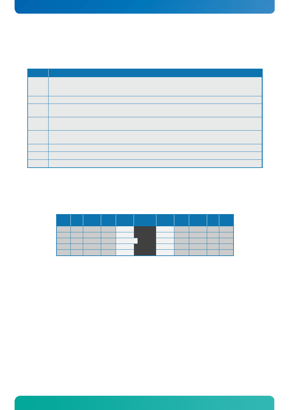
COM1, COM2, COM3 and COM4 Pin Header Connectors
The pinout of Serial ports Com1, 2, 3 and 4 is as follows:
Note Pull
U/D Ioh/Iol Type Signal PIN# Signal Type Ioh/Iol
Pull
U/D Note
-
I
DCD
1 2
DSR
I
-
-
I
RxD
3 4
RTS
O
-
-
O
TxD
5 6
CTS
I
-
-
O
DTR
7 8
RI
I
-
-
-
PWR GND
9 10
5V PWR
-
-
1
Note 1: The COM 1, 2, 3 and 4 header 5V supply is fused with individual 1.1A resettable fuses for each
connector.
A DB9 adapter (ribbon cable) is available for connecting the COM ports to I/O front panel.