FBT DLM26 User Manual
Page 51
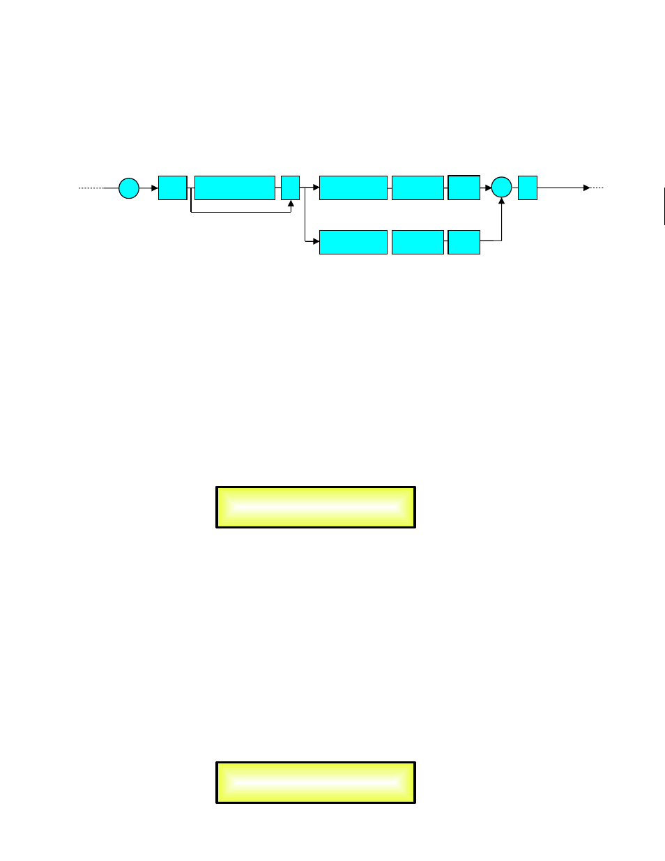
Audio Signal Output Path Block Scheme for the coupled Custom Channels
When working in Custom Mode, 2 channels (one odd and one even) are coupled in order to
provide one “Full Band” output on the odd channel and to use the resources of 2 channels for
featuring the 2 bands compressor and limiter.
The editing of the all parameters of the Coupled Channel, can be done using the buttons of both
coupled channels.
Particularly, accessing the editing pages of the ODD channel of the couple, just pressing the
related EDIT button and turning on the related Blue LED, the all available parameters of the
Standard mode will be accessible with the exception of the ones referring to the RMS compressor
and PEAK Limiter.
Accessing the editing pages of the EVEN channel of the couple, just pressing the related EDIT
button and turning on the related Blue LED, the all available parameters referring to the 2 bands
Rms Compressor and 2 Bands Peak Limiter will be accessible.
“ODD” Channel Editable Parameters
EQ Byp page – from this sub-menu it is possible to Bypass or to make active the 5 Bands
Equalizer placed on the Output Signal Path.
When Bypassed the 5 Bands Equalizer, its current setting will not be lost.
EQ: [x] sub-menu – from this sub-menu it is possible to set the Output Channels five available
Multi-Type Filters.
Anyone of the 5 filters of the Eq can be selected choosing from the list of filter types shown
already at the “Input Path” section
[Peaking_Eq, Hi-Shelv_1, Hi-Shelv_2, Hi-Shelv_Q, Lo-Shelv_1, Lo-
Shelv_2, Lo-Shelv_Q, Low Pass_1, Low Pass_2, Low Pass_Q, High Pass_1, High Pass_2, High Pass_Q, All
Pass_1, All Pass_2, Band Pass, Notch Filt]
More, the DLM26 Is giving the possibility to “Bypass” any single filter of the 5 available in the Equalizer
section; Once in the editing page of the single filter, a “Byp” field is available for making the single filter
active or not.
Name page – from this screen it is possible to assign a 6 character name to the Output Channel.
The following is an example screen for a “Name” page labeled “Low” for Output Channel 1:
5 Band Multi Type
Equalizer
Low Pass
Filter
To X-Over
outputs
From Input
A/B
Delay
Peak
Limiter
Pola
rity
G
Eq
Byp
RMS
Compressor
Peak
Limiter
RMS
Compressor
+
Out-1 Low Name
Name = Low
Out-1 Name EQ Byp
Eq Bypass = Off
High Pass
Filter