Elecraft KAT500 Owners Manual User Manual
Page 42
39
Set the KAT500 on its feet and confirm that all three switches operate smoothly and that all of the
LEDs are in the front panel cutouts. The LEDs should protrude slightly so you can feel them by running
your finger across the panel.
Locate the side panels and clean any tape or residue from the areas around the screw holes on the
inside surface as shown in Figure 33. Check and clean both side panels.
Figure 33. Preparing Side Panels for Installation.
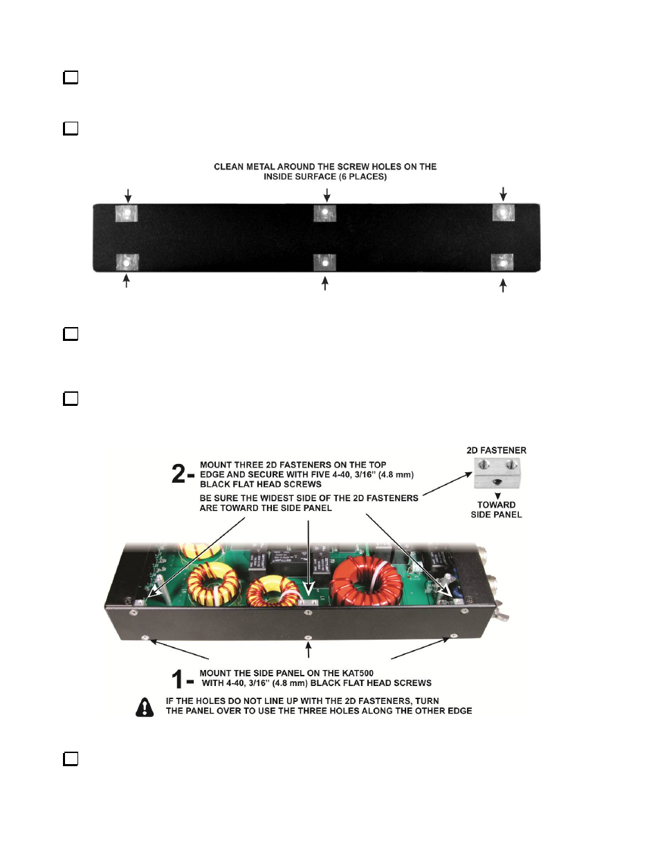
Place a side panel on the KAT500, lining up the three holes along the bottom with the 2D fasteners
between the pc board and the bottom cover. Be sure all three holes line up. If they do not line up, turn the
side panel over to line up the other three holes. Attach the side panel with three screws as shown in
Figure 34 (1).
Mount three 2D fasteners along the top edge of the side pane as shown in Figure 34 (2). Be sure the
widest side is toward the side panel as shown. You may need to loosen the screws along the bottom edge
to allow the panel to move to properly align the holes.
Figure 34. Installing the Side Panels.
Install the second side panel in the same manner as the first.