Elecraft KAT500 Owners Manual User Manual
Page 41
38
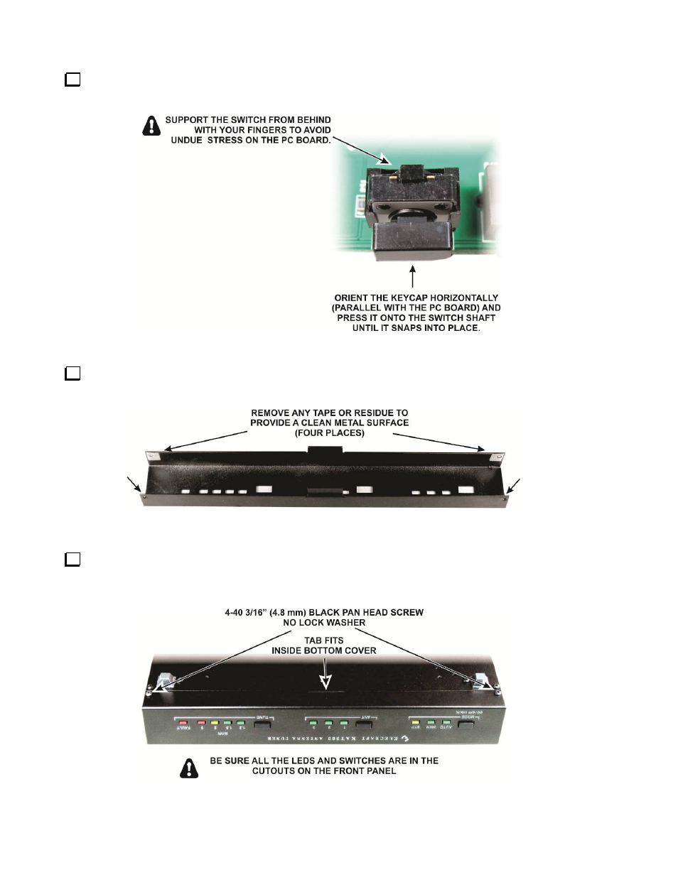
On the edge of the pc board that has the rows of LEDs, install key caps on the three switches (S1, S2
and S3) as shown in Figure 30. Be sure you orient the key caps horizontally (parallel with the pc board).
Figure 30. Installing Key Caps on the Switches.
Locate the front panel and inspect the inside surface around the four screw holes (see Figure 31).
Remove any tape or residue to provide a clean metal surface.
Figure 31. Preparing the Front Panel for Installation.
Turn the KAT500 upside down on your table and mount the front panel as shown in Figure 32. Be
sure that all of the LEDs and switches pass through the openings in the front panel and that the tab at the
center of the front panel fits under the bottom cover, just as on the rear panel.
Figure 32. Mounting the Front Panel.
- KX3 Owner's Manual (58 pages)
- KX3 Assembly Manual (47 pages)
- KX3 Assembly Manual Errata (5 pages)
- KX3-2M (30 pages)
- KX3-PCKT (2 pages)
- KX3 Mobile Installation And Operation Guide (17 pages)
- KX3 Guide for Blind Operators (7 pages)
- KX3 Quick Reference (2 pages)
- K3 Programmers Reference (26 pages)
- KX3 Speaker Grille Instructions (9 pages)
- KXFL3 Filter Option (12 pages)
- KXFL3 Filter Option Errata (2 pages)
- KXAT3 (5 pages)
- KXBC3 (13 pages)
- KXPD3 (4 pages)
- Proset Boom Headset (1 page)
- PX3 Owner's Manual (53 pages)
- PX3 Owners Manual Errata (2 pages)
- KXPA100 Manual (55 pages)
- KXPA100 Assembly Manual (27 pages)
- KXPA100 Assembly Errata (1 page)
- KXPA100 Programmers Reference (24 pages)
- KXAT100 Installation Manual (17 pages)
- KX1 Manual (96 pages)
- KXAT1 (12 pages)
- KXPD1 (7 pages)
- KXB30 (8 pages)
- KXB3080 (20 pages)
- K1 (91 pages)
- K1 1.09 F/W (1 page)
- KNB1 Manual (8 pages)
- KAT1 Manual (15 pages)
- KFL1-2 (2 pages)
- KTS1 (1 page)
- KBT1 Manual (8 pages)
- KBT1 Manual Errata (2 pages)
- K1BKLTKT LCD Mod Kit (6 pages)
- K2 Owner's Manual (171 pages)
- K2 Owner's Manual Errata (1 page)
- K2 PLL (4 pages)
- K2ATOBKIT (15 pages)
- K2ATOBKT (2 pages)
- K2 Keying Modification Instructions (4 pages)
- KPA100 Manual (74 pages)
- KPA100 Shield Upgrade (3 pages)