Elecraft K160RX User Manual
Page 6
6
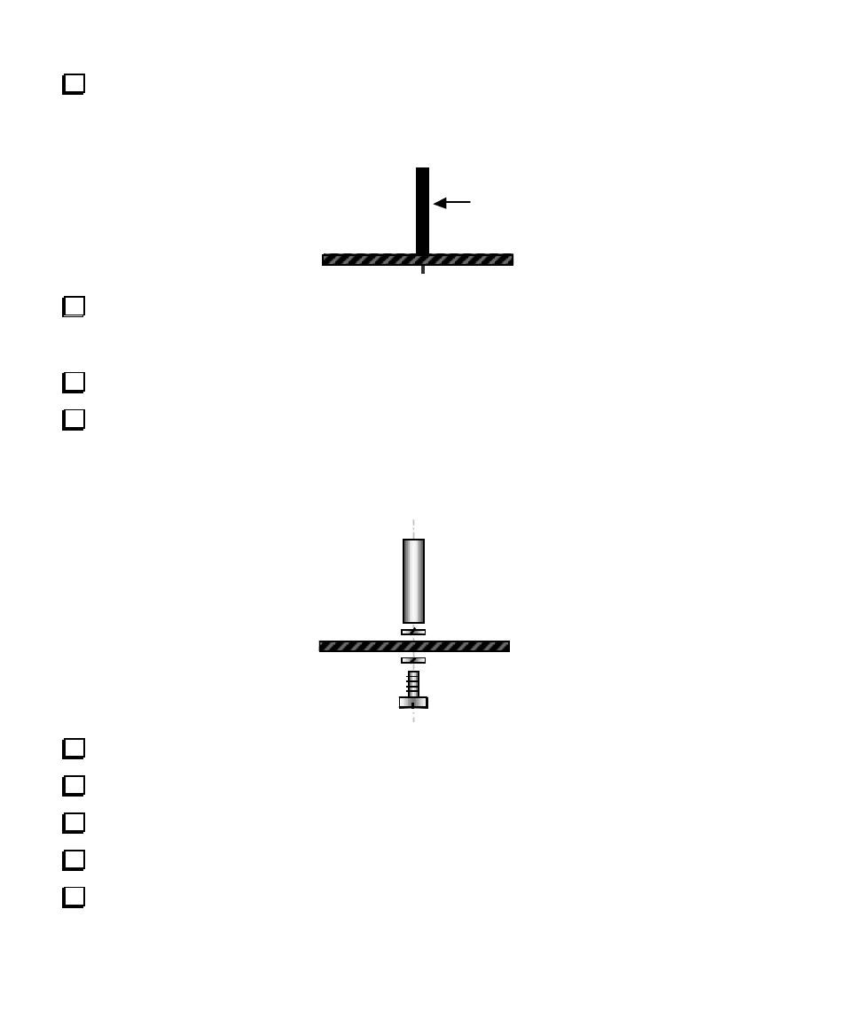
Install the 16-pin female connector on the RF board at J14 as shown by its outline, but do not solder
yet. The side view of J14, below, shows how it should appear once properly seated. This connector is
somewhat fragile because of its height. Be careful not to flex it during installation.
J14
Solder just one pin near the middle of J14, on the bottom of the RF board. Then, if the connector is not
sitting completely flat against the RF board or is not vertical, reheat this pin and carefully press the
connector down. You may hear it snap into place when you heat the pin.
Solder the remaining pins of J14.
Install the 5/8" (16 mm) standoff on the top of the RF board as shown below, using two split lock
washers and a 1/4" (6 mm) machine screw. The mounting hole for the standoff is just to the left of RFC3
(near J14). You must use only one split lock washer between the standoff and the top of the RF board
in order to position the 160-m module at the correct height.
Examine the standoff and its hardware to insure that it does not touch the nearby pad of C113.
If your K2 has a 4.7 pF capacitor at C68 (near T5), replace it with the supplied 10 pF capacitor.
If your K2 has a 39 pF capacitor at C153 (near U10), replace it with the supplied 68 pF capacitor.
Install C75, which is on the left edge of the RF board near K13.
Install C13 and C14 in the band-pass filter section of the RF board, near L3 and L4.