Assembly – Elecraft K160RX User Manual
Page 3
3
Assembly
i
A fine-point, temperature-controlled soldering iron is required to assemble this kit. A high-
wattage iron may damage components, pads, or traces.
i
In the following steps you'll be installing the latching relays (K1 and K2). Relay pins must not be
bent or trimmed as this may cause unreliable mechanical operation.
Place relays K1and K2 on the top side of the 160 meter PC board (component side). One end of each
relay has a heavy line printed across the top to indicate the pin 1 end. This end must be matched with the
s
ame
end
of
t
he
r
e
l
ay’
s
PC
boa
r
d
out
l
i
ne
.
Do
not
s
ol
de
r
t
he
r
e
l
ays
yet
.
Solder only two pins on each relay, at opposite corners. Do not bend or clip relay leads.
Verify that the relays are in the correct orientation and are seated flat on the board, then solder all of
the remaining relay pins.
Install all of the capacitors (C1-C6), bending the leads out slightly on the bottom to hold them in
place. Trim the leads to about 1/16" (1.5 mm) long before soldering to insure that the leads do not come
into contact with the toroids on the main board.
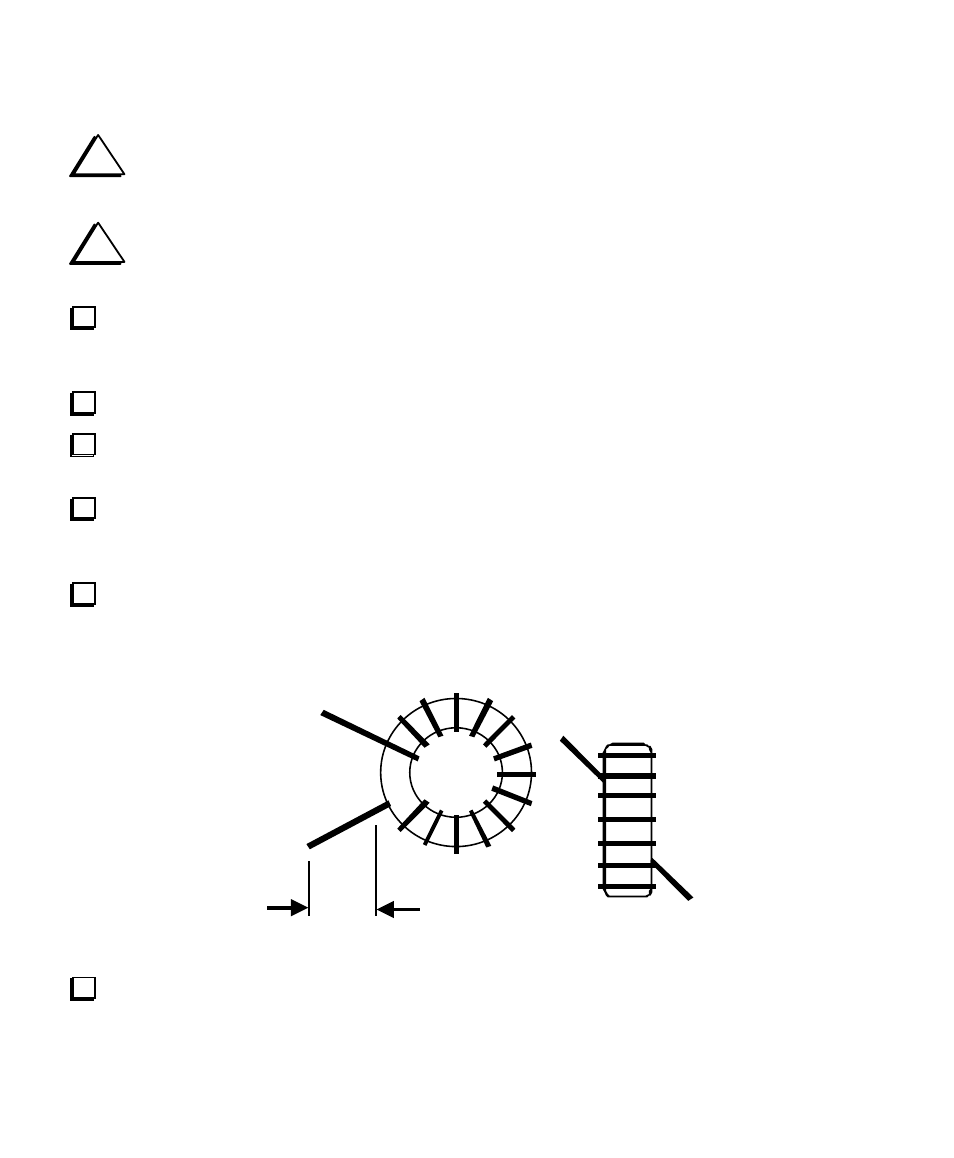
Inductor L1 is wound on a T44-1 or T50-1 toroidal core (blue) using 17 inches (43 cm) of #26 enamel
wi
r
e
.
To
wi
nd
t
he
i
nduct
or
,
“
s
ew”
t
he
l
ong
e
nd
of
t
he
wi
r
e
t
hr
ough
t
he
c
or
e
e
xa
c
t
l
y
21
t
i
me
s
.
Each pass
through the core counts as one turn. The finished winding should look very similar to the drawing below,
but with 21 turns rather than 14.
Remov e insu lation
Ve
r
i
f
y
t
ha
t
t
he
t
ur
ns
of
L1
a
r
e
not
bunche
d
t
oge
t
he
r
.
The
y
s
houl
d
oc
c
upy
a
bout
85%
of
t
he
c
or
e
’
s
circumference as shown above.