P1 (onbo ttom) componen ts on top – Elecraft K160RX User Manual
Page 4
4
Cut L1's leads to about 1/2" (12 mm) long. Completely remove the enamel insulation from the leads
t
o
wi
t
hi
n
1/
16”
(
1.
5
mm)
of
t
he
c
or
e
.
To
r
e
move
t
he
i
ns
ul
a
t
i
on,
us
e
your
s
ol
de
r
i
ng
i
r
on
t
i
p
(
a
nd
a
l
i
t
t
l
e
solder), a butane lighter, or sand-paper. If you scrape the insulation off, be careful not to nick the wire.
Install L1 flat against the PC board as shown by its component outline, then pull the leads taut on the
bottom of the board. Note: The correct holes for L1's leads are both just to the right of the component
outline. Do not use the hole near the "L1" label.
Trim and solder the leads of L1. When soldering, make sure that the solder binds well to the leads. If
t
he
l
e
a
d
a
ppe
a
r
s
t
o
be
a
n
“
i
s
l
and”
i
n
a
s
ma
l
l
pool
of
s
ol
de
r
,
c
ha
nc
es
a
r
e
i
t
i
s
not
maki
ng
good
c
ont
a
c
t
.
I
t
’
s
a
good idea to measure from pad to pad using an ohmmeter to be sure the leads are making contact.
Wind and install L2 in exactly the same way as L1.
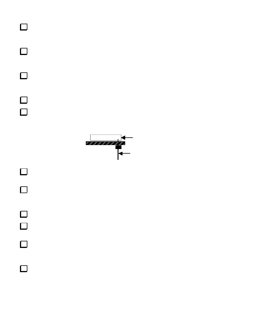
Install 16-pin male connector P1 on the bottom of the PC board in the position indicated by its
component outline. Do not solder yet. The drawing below shows how P1 should appear viewed from the
left end of the board, with the notch towards you and the component side up.
P1 (onbo ttom)
Componen ts on top
Solder just one pin of P1, near the middle of the connector (close to relay K1 on the top side of the
board). Be careful not to touch K1's plastic case with the soldering iron.
Verify that P1 is now perpendicular to the PC board and is seated completely flat. If not, re-heat the
soldered pin and press down on all of P1's pins until the connector drops into place. Once the connector is
seated correctly, solder the remaining 15 pins.
Cut a 1.5" (3.8 cm) length of hookup wire. Remove 1/4" (6 mm) of insulation from each end.
Solder one end of this wire to the pad labeled "RX" near the notch in the 160-m PC board. The other
end will be connected to the center terminal of the receive antenna jack (K160-J1) in a later step.
Prepare a second 1.5" (3.8 cm) wire. Solder one end of this wire to the ground pad just to the left of
C5 on the 160-m PC board. This pad is not labeled. The other end will later be connected to the solder lug
of the receive antenna jack.
Inspect the 160-meter module for solder bridges or cold solder joints, especially around P1.