Elecraft KXB3080 User Manual
Page 7
7
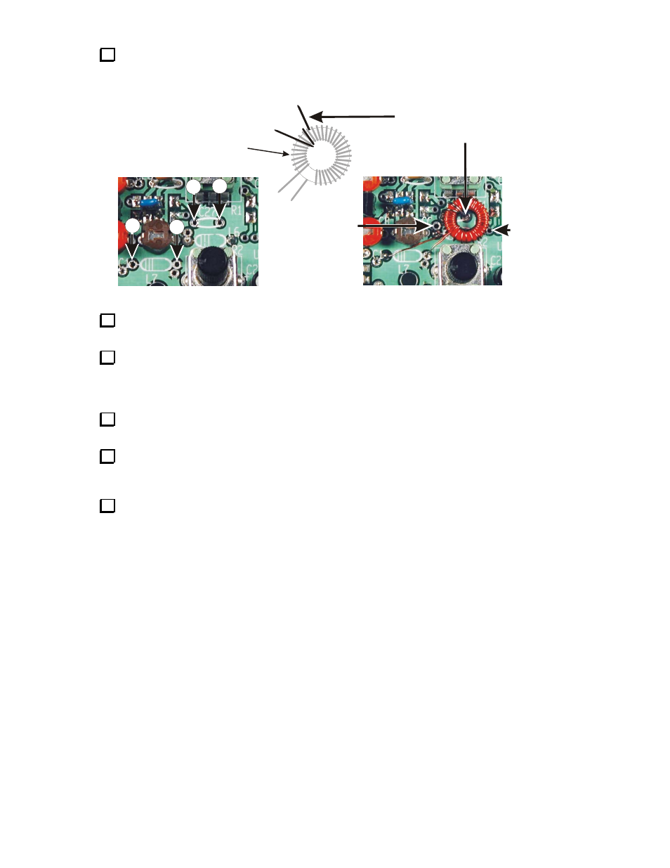
Position T2 between potentiometers R1 and R2 as shown in Figure 4 with the leads passing through
the pads for C27 and L7 as shown in Figure 4. Mark each lead where it enters the pad. Use a marker or
place a slight bend in the wire at that point.
Lead 2 goes straight down
through the center of the
core into the solder pad.
Direction of each winding
and position of windings
must be exactly as
shown.
Via (Hole
through
PCB)
must be
clear.
Position T2 so
Solder Pad CC
and Via (Hole
through PCB) on
opposite side
are clear.
4
3
1
2
Lead Connection Points
Transformer T2
Installed Transformer
2
1
3
4
Figure 4. Winding and Installing Transformer T2.
Remove T2, strip the insulation and tin the leads of both windings back to the points you marked in
the previous step.
Replace T2 on the PCB, drawing the leads through the proper solder pads as shown in Figure 4.
Position T2 exactly as shown. Solder pad CC on one side of T2 and the hole through the circuit via on the
other side of T2 must be clear. Be sure a small segment of tinned wire is visible above the solder pad on the
toroid side of the PCB on each lead. If not, strip a little more enamel off of that lead before proceeding.
Solder all four leads and trim them flush on the opposite side of the PCB. Be careful not to pull T2 out
of position while soldering.
Bend a discarded component lead into a “U” shape and insert it into J7 pins 1 and 3. J7 is the 3-pin
connector adjacent to antenna jack J2. It is visible with the jumper in place at the top left corner of Figure 2.
This jumper completes the antenna circuit when the optional KXAT1 ATU is not installed.
Refer to your KX1 Owner’s Manual, Alignment and Test – Part II and perform the Receiver Alignment
to confirm that the modifications have been installed correctly and the receiver is working as expected on
40 and 20 meters. These tests may be done with the KX1 out of its case.