Operation, Circuit details, Receiver input filter changes on the kx1 main pcb – Elecraft KXB3080 User Manual
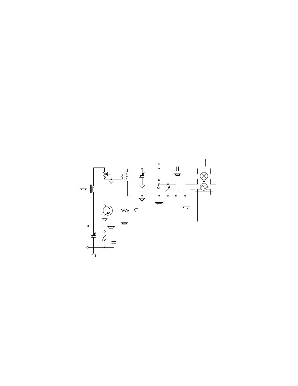
Page 18: Figure 15. receiver input schematic diagram
18
Operation
The operation of your KX1 is the same as before, except now when you cycle through the bands you will
also have the option of selecting 30 and 80 meters. Like the other bands, the tuning range on 30 and 80
meters extends well outside the Amateur bands to include popular SWL frequencies. The KXB3080 also
improves sensitivity in the popular 49-meter SWL band (5.9 – 6.2 MHz) by automatically re-resonating the
input circuit when tuning those frequencies. On 80 meters, the tuning range extends from 5.5 MHz down to
about 1 MHz, although the sensitivity will decrease rapidly outside of the 3.5 – 4.0 MHz range.
The KXAT1 antenna tuner also functions normally on the 80 and 30 meter ranges, although its matching
range is limited on 80 meters. If you want a greater matching range on 80 meters, you might experiment
with adding turns to the toroids in the KXAT1. Doubling the number of turns on toroidal inductors L1, L2
and L3 in the KXAT1 will improve the matching range on 80 meters substantially, while reducing the
matching range on the higher frequency bands.
Circuit Details
Receiver Input Filter Changes on the KX1 Main PCB
The original KX1 receiver input circuit uses a capacitive divider. It is optimized for ease of construction,
and can be tuned to 40 through 20 meters. To accommodate 80 meters, the circuit must be reconfigured as
link-coupled; this is the function of the new transformer T2 (see Figure 15). Capacitor value changes are
also necessary to provide the best overall performance on all bands.
Rcv Mixer
V-
V+
1
2
3
3
7
7
4
5
6
U6
R1
C15
. 01
C B
C1
15
K1B
Solder pads originally for L7.
Solder pads originally for C27.
2
4
C C
5 0
NE602
RF Gain
L 6
6.8 μH
1 K
C
C A
2 0
K1A
5
6
RX ANT
2N4124
Q7
R2
1.K
6T_2
B
A
C26
5 6
C56
6
T2
2
1
4
3
3 & 4:
1 & 2:
Figure 15. Receiver Input Schematic Diagram.