Elecraft KXB3080 User Manual
Page 5
5
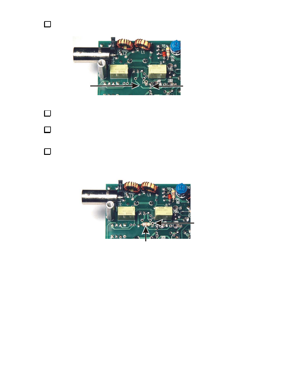
Turn the KX1 PCB over and cut the trace from CB to C27/R1 as shown in Figure 2. Use a sharp
hobby knife and cut across the trace several times as needed to cut through the metal.
Cut Circuit
Trace Here
Jumper from Trace
to Grounded Pad of
Trimmer Capacitor CC
Figure 2. Modifying Trace From Capacitor CB.
Use your DMM to confirm that the cut trace is an open circuit. Check the resistance between a solder
pad on one part of the cut trace and a solder pad on the other part. It should be greater than 1 megohm.
Scrape off the green coating and tin a short length of the trace adjacent to the pad for trimmer
capacitor CC. Use a cut lead to form a short jumper between the trace and the grounded end of CC as
shown in Figure 2.
Remove molded inductor L6 from the top side of the PCB (see Figure 1) and reinstall it on the bottom
of the PCB as shown in Figure 3. Be sure you place the leads in the same solder pads L6 originally
occupied. In case you damage the inductor while removing it, a replacement is provided: 6.8 µH (blu-gry-
gld). When soldering L6 in place, do not fill the pad for connection A. This pad will be needed later to
attach the KXB3080 module. Trim L6’s leads flush with the top of the PCB.
Keep
Pad "A"
Clear.
L6
Figure 3. L6 Relocated on Bottom of KX1 PCB.