Dynojet 250iPX: Installation Guide User Manual
Page 24
Model 200iPX/250iPX Upgrade Installation Guide
C H A P T E R 1
Dyno Preparation
1-16
I
NSTALLING
THE
M
ONITOR
A
RMS
, M
ONITOR
T
RAY
,
AND
L
EFT
B
LOWER
A
SSEMBLY
1
Replace the monitor arms, washers, and tray.
2
Connect the cables removed earlier to the control pod and monitor arms.
Refer to the model 200iP/250iP installation guide for more information.
3
Replace the left blower assembly.
Note: The right blower assembly will be installed later.
4
Remove the two 1/4-20 screws securing the upright bar and set aside.
5
Remove the upright and set aside.
Note: The upright bar will be installed on the iPX drum module later.
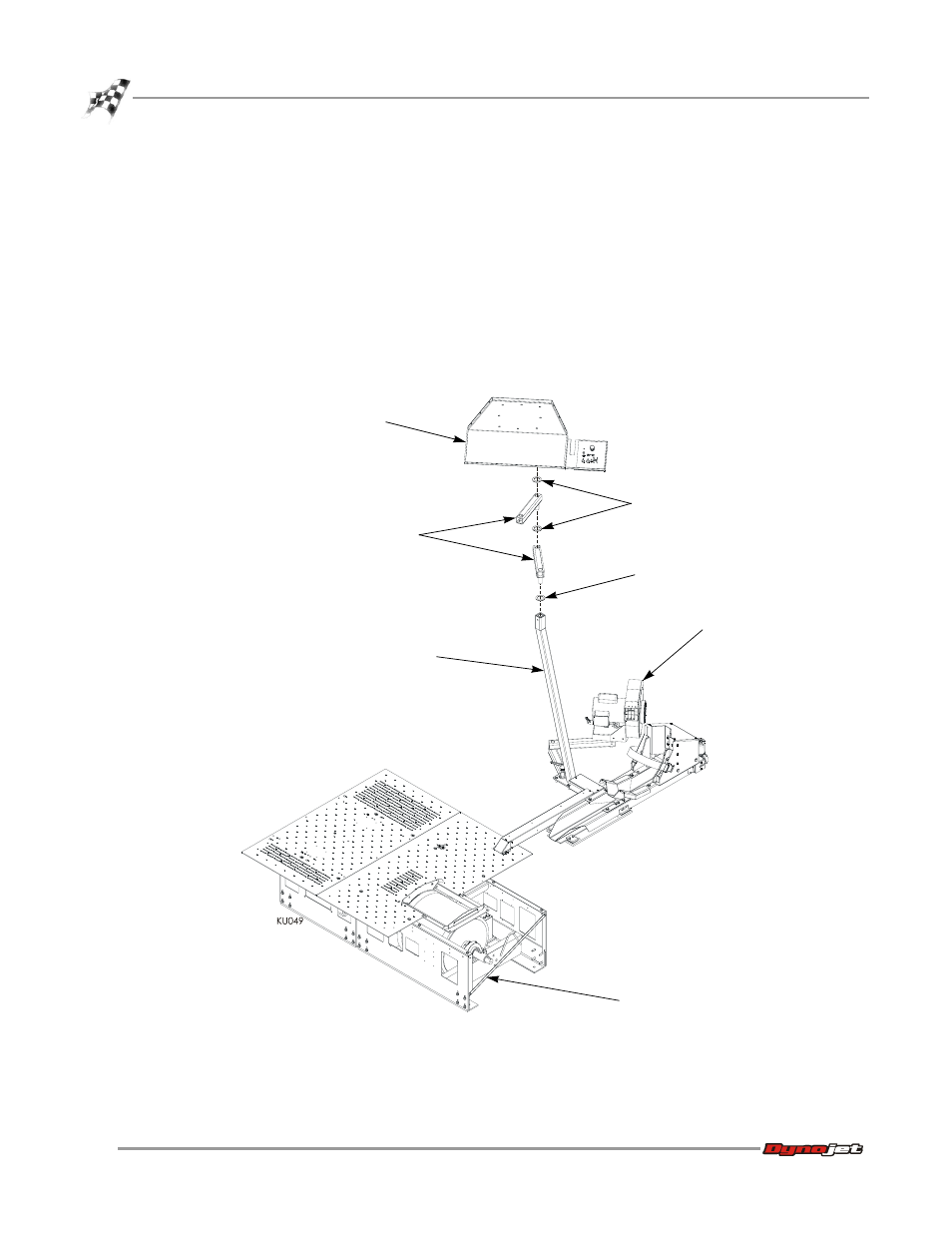
Figure 1-13: Installing the Monitor Arms, Monitor Tray, and Left Blower Assembly
monitor
support
washer
tray
arms
washers
left blower
assembly
upright bar
This manual is related to the following products: