Removing the right side drum cover – Dynojet 250iPX: Installation Guide User Manual
Page 18
Model 200iPX/250iPX Upgrade Installation Guide
C H A P T E R 1
Dyno Preparation
1-10
R
EMOVING
THE
R
IGHT
S
IDE
D
RUM
C
OVER
1
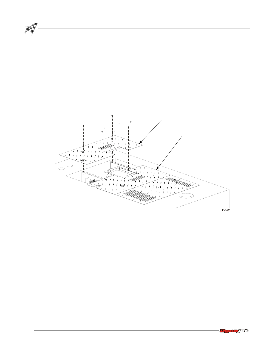
Remove the four 3/8-16 x 1/2-inch button-head flange screws securing the right
side drum cover to the dyno and set aside.
2
Remove the four 1/4-20 x 1/2-inch button-head flange screws securing the right
side drum cover to the drum guard bracket and set aside.
3
Remove the right side drum cover and discard. This cover will be replaced.
4
Remove the four 3/8-16 x 1/2-inch button-head flange screws securing the middle
drum cover to the dyno and set aside.
Note: You do not need to remove the cover. Removing the screws will allow the
cables to be routed under this cover later.
Figure 1-7: Remove the Right Side Drum Cover
right side drum cover
middle drum cover