Removing the monitor support and junction box – Dynojet 250iPX: Installation Guide User Manual
Page 21
M O D E L 2 0 0 I P X / 2 5 0 I P X U P G R A D E
Dyno Preparation
Version 1
Model 200iPX/250iPX Upgrade Installation Guide
1-13
R
EMOVING
THE
M
ONITOR
S
UPPORT
AND
J
UNCTION
B
OX
1
Remove the left blower assembly if installed.
2
Remove the four 3/8 x 1-inch bolts and four washers securing the left blower
mount and set aside. Do not remove the blower mount.
3
Remove the right blower assembly.
4
Remove the four 3/8 x 1-inch bolts and four washers securing the support arm
and junction box to the pit floor and set aside.
5
Remove the junction box and set aside.
6
Remove the support arm and move to the left blower mount.
7
Set the right blower mount aside. This will be installed in a new location.
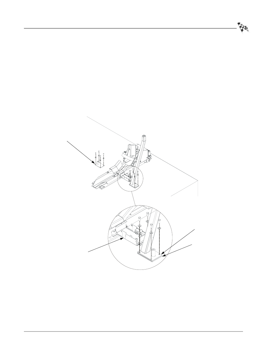
Figure 1-10: Remove the Monitor Stand and Junction Box
PD039
support arm
blower mount
junction box
right blower mount
(under support arm)