Dynojet 250iPX: Installation Guide User Manual
Page 23
M O D E L 2 0 0 I P X / 2 5 0 I P X U P G R A D E
Dyno Preparation
Version 1
Model 200iPX/250iPX Upgrade Installation Guide
1-15
I
NSTALLING
THE
J
UNCTION
B
OX
C
OVER
, E
ND
C
AP
,
AND
C
ABLE
C
OVER
1
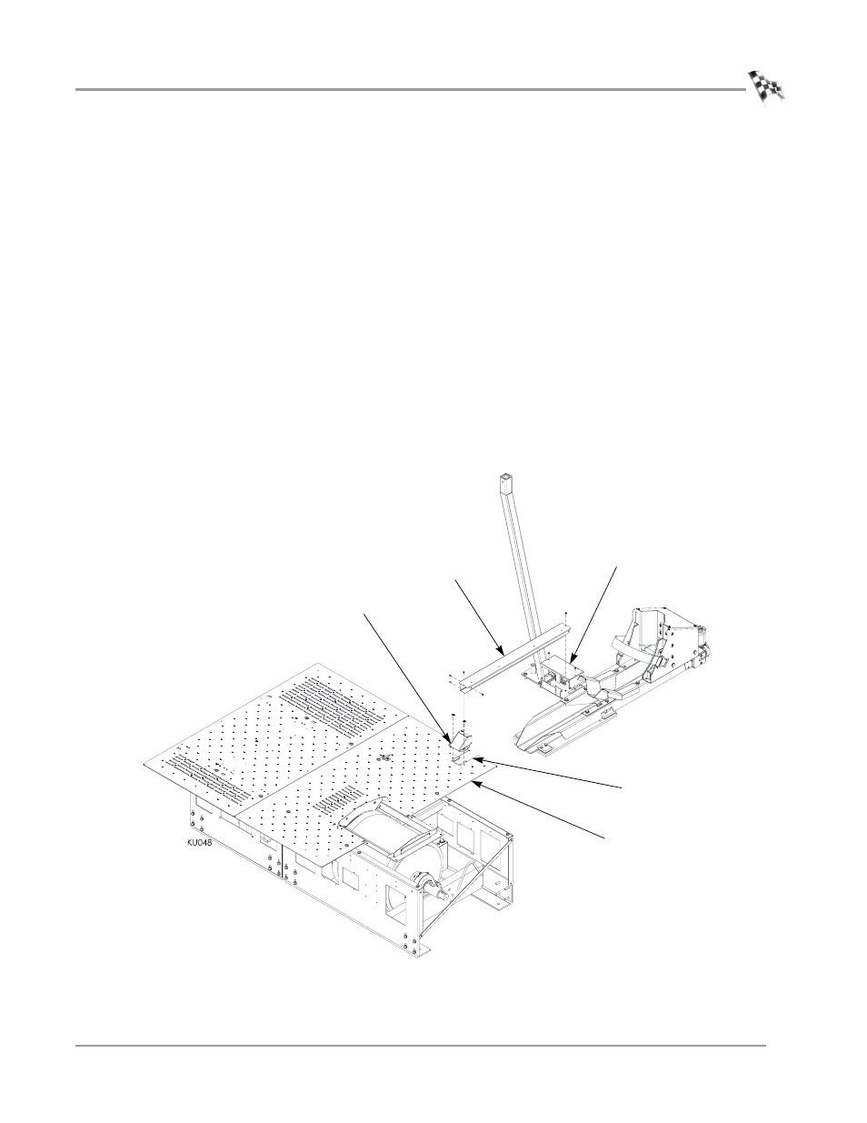
Remove the four screws securing the cable routing cover to the middle drum
cover. Set the screws and the cover aside.
2
Route all the cables under the middle drum cover and through the cable routing
opening as shown in Figure 1-12.
3
Replace the four 3/8-16 x 1/2 button-head flange screws removed earlier from the
middle drum cover.
4
Route the cables through the junction box.
5
Secure the junction box cover to the junction box using the two 8-32 screws
removed earlier.
6
Secure the end cap to the pit cover using the two 1/4-20 button-head screws
removed earlier.
7
Secure the cable cover to the end cap using the four 8-32 screws removed earlier.
8
Secure the cable cover to the junction box cover using one 8-32 screw removed
earlier.
Note: Verify the cables are placed inside the cable cover.
Figure 1-12: Install the Junction Box Cover, End Cap, and Cable Cover
junction box cover
cable cover
end cap
middle drum cover
cable routing
opening