Dynojet 250iPX: Installation Guide User Manual
Page 16
Model 200iPX/250iPX Upgrade Installation Guide
C H A P T E R 1
Dyno Preparation
1-8
R
EMOVING
THE
C
ABLE
C
OVER
, E
ND
C
AP
,
AND
J
UNCTION
B
OX
C
OVER
If your monitor stand is mounted on the left side of your dyno, skip to “Removing the
Right Side Drum Cover” on page 1-10.
If this is a new dyno installation, skip to “Installing the Monitor Support and the
Junction Box on the Left Side” on page 1-14.
1
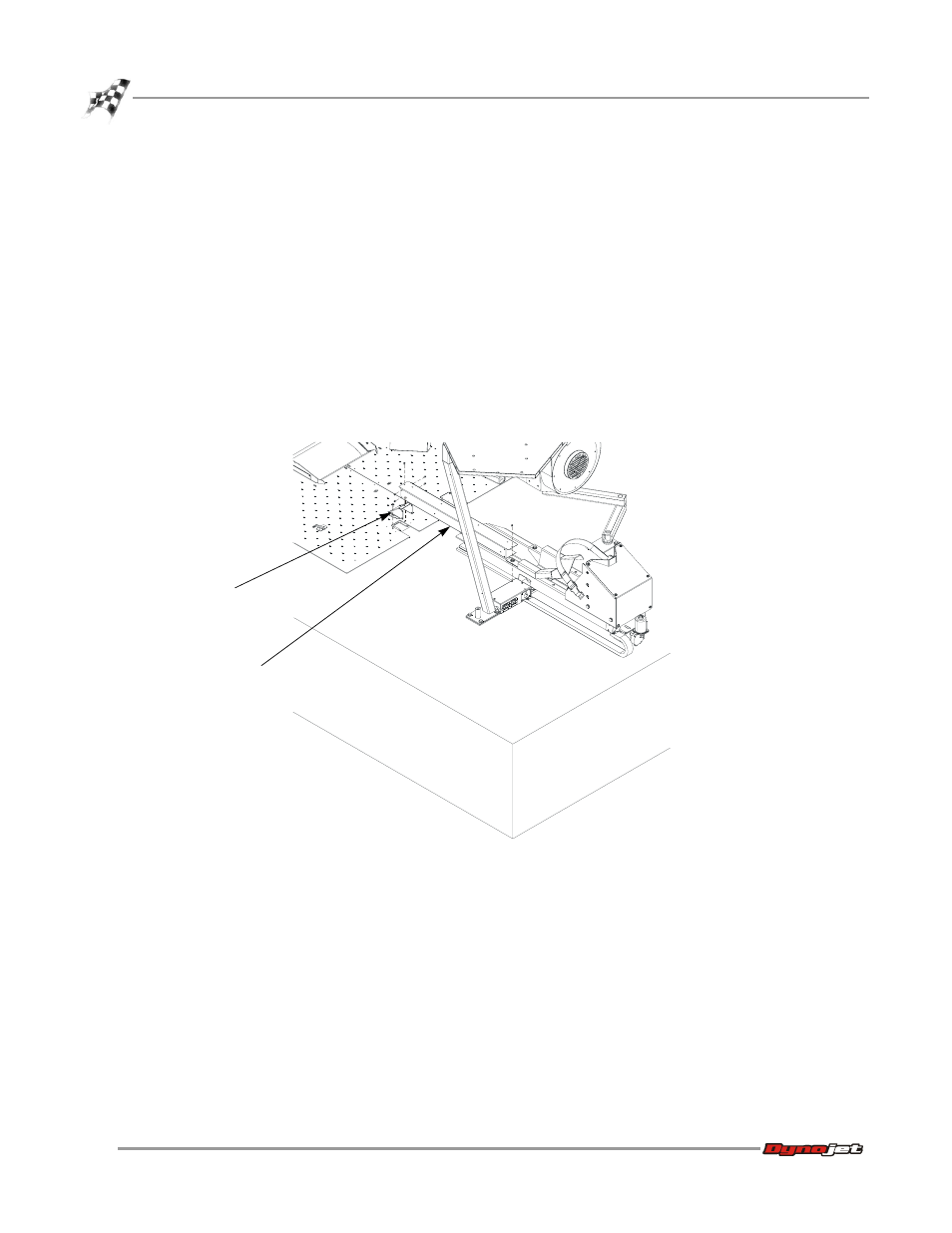
Remove the four 8-32 screws securing the cable cover to the end cap and
one 8-32 screw securing the cable cover to the junction box and set aside.
2
Remove the cable cover and set aside.
3
Remove the two 1/4-20 button-head screws securing the end cap to the pit cover
and set aside.
4
Remove the end cap and set aside.
Figure 1-5: Remove the Cable Cover and End Cap
PD042
end cap
cable cover