Wiring schematics for different applications – Detex DS-1581 User Manual
Page 2
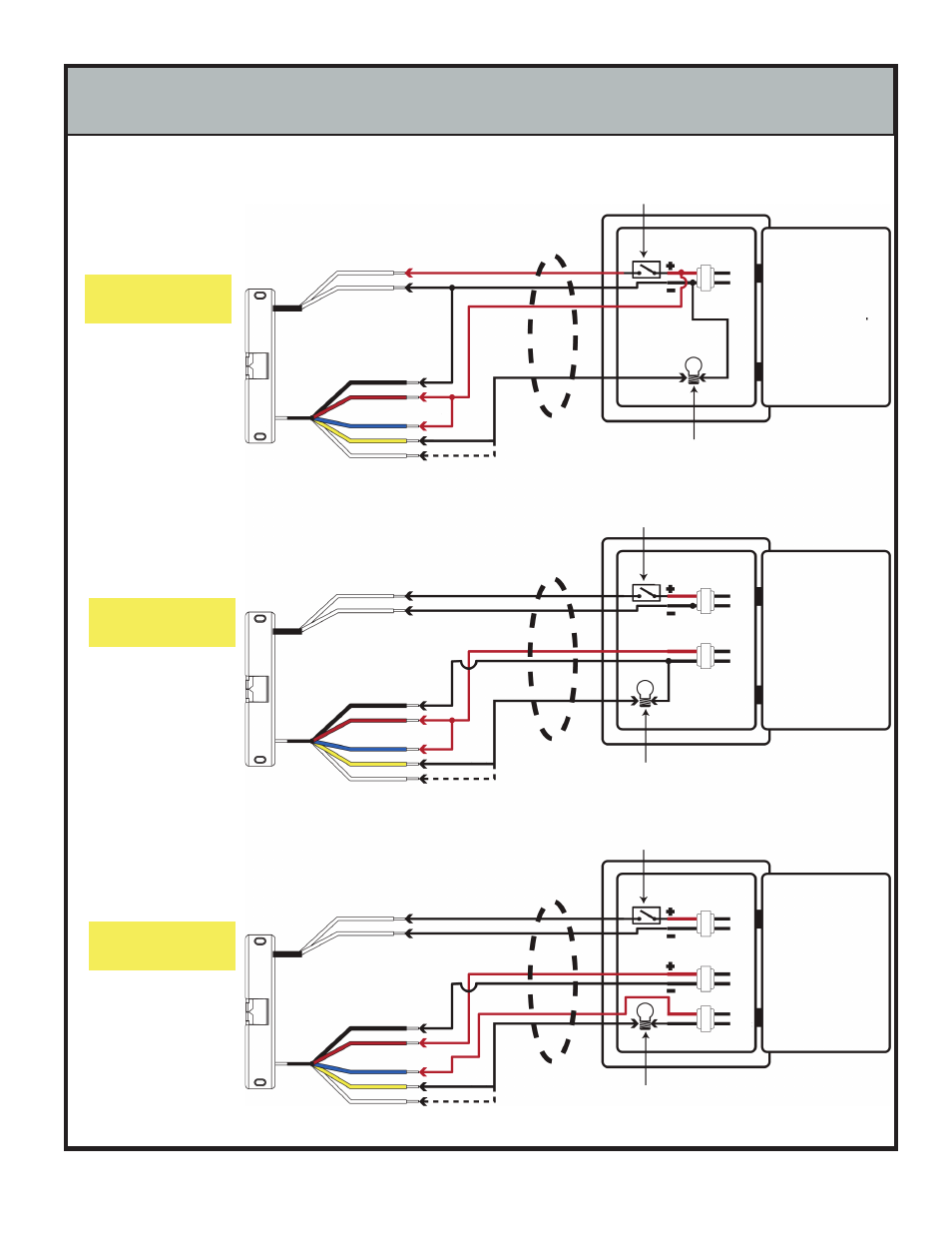
WIRING SCHEMATICS FOR DIFFERENT APPLICATIONS
FRAME SIDE
WIRING
PANEL SIDE
WIRING
FRAME SIDE
WIRING
PANEL SIDE
WIRING
FRAME SIDE
WIRING
PANEL SIDE
WIRING
CONTROL
PANEL
CONTROL
PANEL
CONTROL
PANEL
FOUR WIRE
SCHEMATIC UTILIZING
ONE TRANSFORMER
FIVE WIRE SCHEMATIC
UTILIZING TWO
TRANSFORMERS
SIX WIRE SCHEMATIC
UTILIZING THREE
TRANSFORMERS
This wiring arrangement
uses the least amount of
conductors between the
Panel and the Frame.
If the Signaling Device or
Panel Indicator requires a
different voltage, this
wiring scheme can be
used.
This wiring arrangement
is used to isolate the
strike operation, from the
LB sensor power board
and finally the Panel
Indicator or Signaling
Device.
STRIKE POWER
WIRE LEADS
LB SENSOR POWER
WIRE LEADS
LB SENSOR SIGNAL
WIRE LEADS
STRIKE POWER
WIRE LEADS
LB SENSOR POWER
WIRE LEADS
LB SENSOR SIGNAL
WIRE LEADS
STRIKE POWER
WIRE LEADS
LB SENSOR POWER
WIRE LEADS
LB SENSOR SIGNAL
WIRE LEADS
BLUE COMMON (
COM)
YELLOW - NORMALLY OPEN (
NO)
WHITE - NORMALLY CLOSED (
NC)
BLACK -
RED +
BLACK -
RED +
BLUE COMMON (
COM)
YELLOW - NORMALLY OPEN
(NO)
WHITE - NORMALLY CLOSED (
NC)
BLACK -
RED +
BLUE COMMON (
COM)
YELLOW - NORMALLY OPEN (
NO)
WHITE - NORMALLY CLOSED (
NC)
Hook-up to either
Normally Open
or Normally
Closed Terminal
Hook-up to either
Normally Open
or Normally
Closed Terminal
Hook-up to either
Normally Open
or Normally
Closed Terminal
PANEL INDICATOR
OR OTHER
SIGNALING DEVICE
PANEL INDICATOR
OR OTHER
SIGNALING DEVICE
PANEL INDICATOR
OR OTHER
SIGNALING DEVICE
CONTROL SWITCH
OR RELAY
12VDC
OUTPUT
POWER
SUPPLY
120
VAC
120
VAC
120
VAC
120
VAC
120
VAC
120
VAC
POWER
SUPPLY 3
POWER
SUPPLY 1
POWER
SUPPLY 2
POWER
SUPPLY 1
POWER
SUPPLY 2
12 - 24 VDC
OUTPUT
12 - 24 VDC
OUTPUT
12 - 24 VDC
OUTPUT
12 - 24 VDC
OUTPUT
CONTROL SWITCH
OR RELAY
CONTROL SWITCH
OR RELAY