Salter Brecknell 7550 User Manual
Page 8
If Number of Turns is positive value, turn potentiometers
clockwise. If Number of Turns is a negative value, turn potentio-
meters counterclockwise.
6. Repeat Steps 3a through 3c, checking all weight sensors with test
weights, to make sure you have properly adjusted J-Box
potentiometers.
If displayed weight value for any weight sensor varies from the
others by more than ±1 scale division, then repeat Steps 3 through
5 until you achieve equal readings.
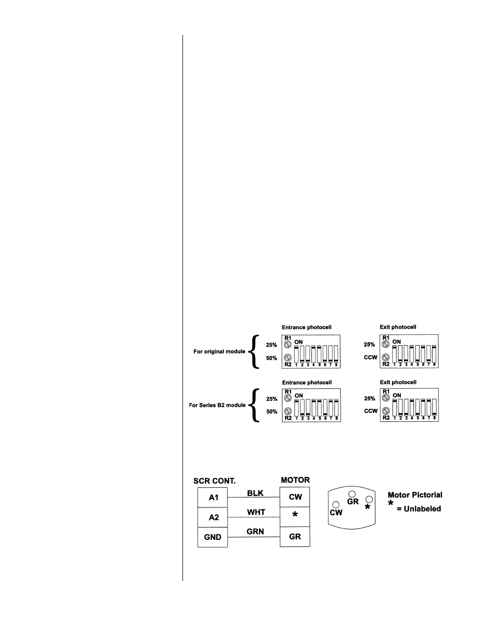
The photocells contain programmable modules. Remove the back cover
of the photocell case. The programming switches on the modules need
to be positioned correctly for the photocells to function properly. See
Figure 2 for programming switch positions. R1 and R2, as seen in Figure
2, are one-turn potentiometers. Turn them as labeled for proper
function. (CCW means fully counterclockwise and 50% means turned
halfway between the fully CCW and fully CW positions, etc.)
Use the first set of illustrations in Figure 2 if you have the original (non-
B2 series) photocell. Use the second set of illustrations if the photocells are
the Series B2 type. Note that the only difference between the two types is
the position of switches 7 and 8. Switches 1-6 remain the same.
Below are diagrams for wiring the optional speed controller to the DC motor.
Photocell
Programmable
Modules
Figure 2
Photocell Module
Programming
IMPORTANT: If you have a photocell with a
Series B2 designation on the cover label, be
sure to use the appropriate illustration of your
module.
Optional DC Motor Speed
Control Wiring
5