Salter Brecknell 7550 User Manual
Page 7
5. Material breaks beam of exit photocell…
Weight is displayed and transmitted to a peripheral device.
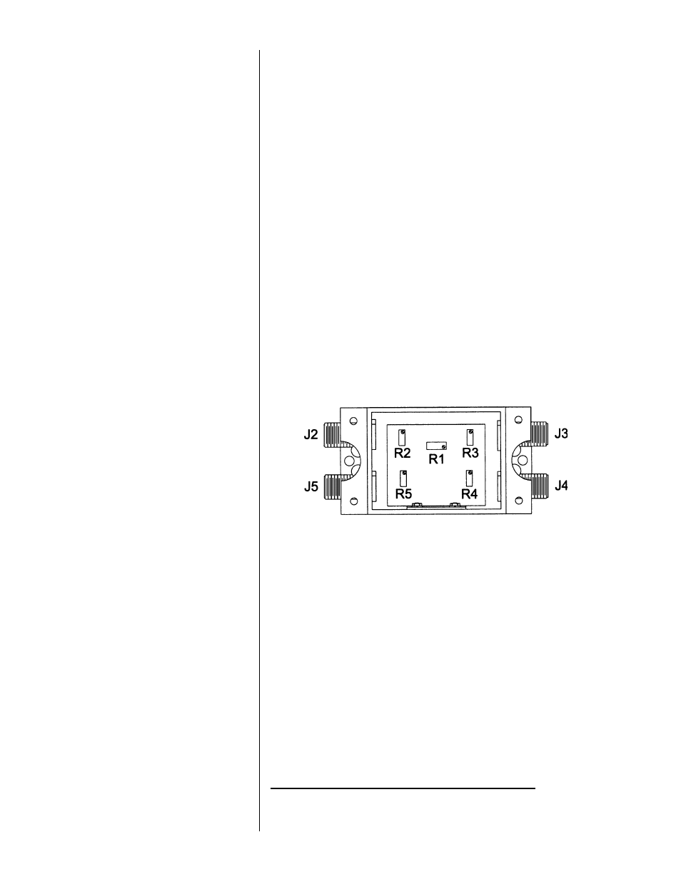
This scale uses a junction box (J-Box) where the outputs of multiple Weigh
Bars of matching capacities are added together. The J-Box then sends a
single signal to the indicator. These multiple signals must be balanced for
the scale to function properly. This is done at the factory, but these
instructions are provided in case they are needed. Figure 1 illustrates the
type of J-Box in the conveyor scale. Each potentiometer affects one weight
sensor. Balance the weight sensors by adjusting potentiometers in the J-
Box as follows:
1. Remove J-Box cover to access potentiometers.
2. Use R1 to set the zero value required by the indicator.
3. Use a test weight that does not exceed the capacity of one weight
sensor, usually 1/4 scale capacity, and obtain a displayed weight
value for the test weight applied to each weight sensor in the scale
system, like this:
a. Place certified test weight directly above first weight sensor.
b. Record displayed weight value.
c. Remove test weight and verify the display returns to zero before
reloading another weight sensor.
d. Repeat Steps a through c for each weight sensor in the scale
system.
4. If displayed weight value for any weight sensor varies from the others
by less than ±1 division, proceed to calibration of the WI-127 if
necessary.
5. If displayed weight value for any weight sensor varies from the others
by more than ±1 division, adjust J-Box potentiometers by turning them
the number of 360° turns indicated by this formula:
Balancing Weigh Bars
Routed Through a
JunctionBox
Figure 1
Weigh Bar J-Box
R1-Course Zero
R2-J2
R3-J3
R4-J4
R5-J5
4
= Number of Turns
Certified Test Weight Value - Displayed Weight Value
Certified Test Weight Value x 0.0028