Carrier 50TC User Manual
Page 9
9
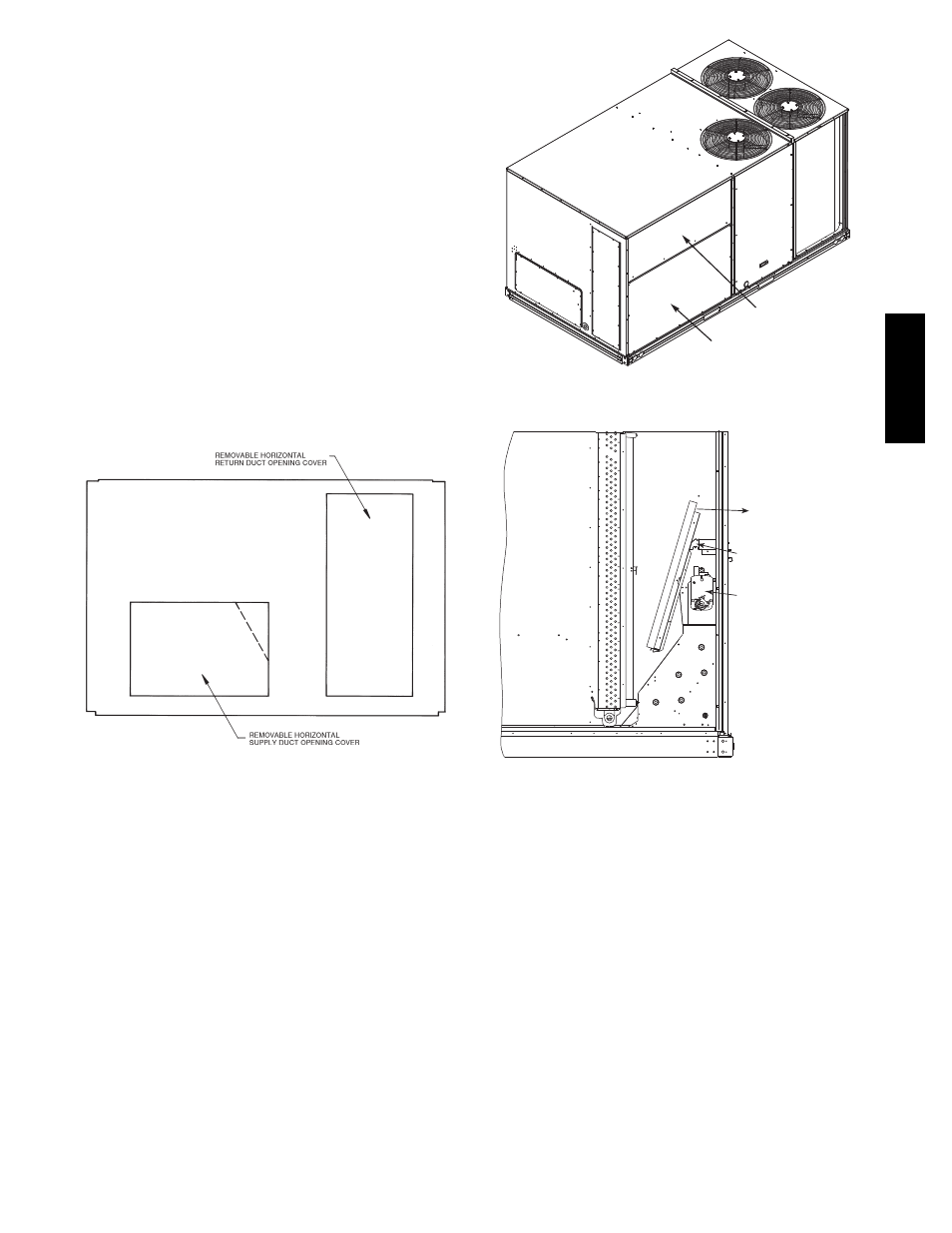
Step 7 — Convert to Horizontal and Connect
Ductwork (when required)
Unit is shipped in the vertical duct configuration. Unit
without factory--installed economizer or return air smoke
detector option may be field--converted to horizontal ducted
configuration using accessory CRDUCTCV001A00. To
convert to horizontal configuration, remove screws from side
duct opening covers and remove covers.
Discard the supply duct cover. Install accessory
CRDUCTCV001A00 to cover the vertical supply duct
opening. Use the return duct cover removed from the end
panel to cover the vertical return duct opening.
Field--supplied flanges should be attached to horizontal
duct openings and all ductwork should be secured to the
flanges. Insulate and weatherproof all external ductwork,
joints, and roof or building openings with counter flashing
and mastic in accordance with applicable codes.
Do not cover or obscure visibility to the unit’s informative
data plate when insulating horizontal ductwork.
C06108
Fig. 8 -- Horizontal Conversion Panels
Step 8 — Install Outside Air Hood
Economizer Hood Removal and Setup --
Factory Option —
1. The hood is shipped in knock--down form and located
in the return air compartment. It is attached to the
economizer using two plastic tie--wraps.
2. To gain access to the hood, remove the filter access
panel. (See Fig. 9.)
3. Locate and cut the (2) plastic tie--wraps, being careful
to not damage any wiring. (See Fig. 10.)
4. Carefully lift the hood assembly through the filter
access opening and assemble per the steps outlined in
Economizer Hood and Two–Position Hood on page 10.
FILTER ACCESS PANEL
INDOOR COIL ACCESS PANEL
C10004
Fig. 9 -- Typical Access Panel Locations
Economizer
Cut Plastic Ties
(2) Places
Remove Hood Parts
C10005
Fig. 10 -- Economizer Hood Package Location
Two Position Damper Hood Removal and Setup --
Factory Option —
1. The hood is shipped in knock--down form and
assembled to a metal support tray using plastic stretch
wrap. Located in the return air compartment, the
assembly’s metal tray is attached to the basepan and
also attached to the damper using two plastic
tie--wraps.
2. To gain access to the hood, remove the filter access
panel. (See Fig. 9.)
3. Locate the (2) screws holding the metal tray to the
basepan and remove. In order to remove the screws, it
may be necessary to remove the panel underneath the
two--position damper. Remove the two screws. Locate
and cut the (2) plastic tie--wraps securing the
assembly to the damper. (See Fig. 11.) Be careful to
not damage any wiring or cut tie--wraps securing any
wiring.
50TC
--
*16