Carrier 50TC User Manual
Page 18
18
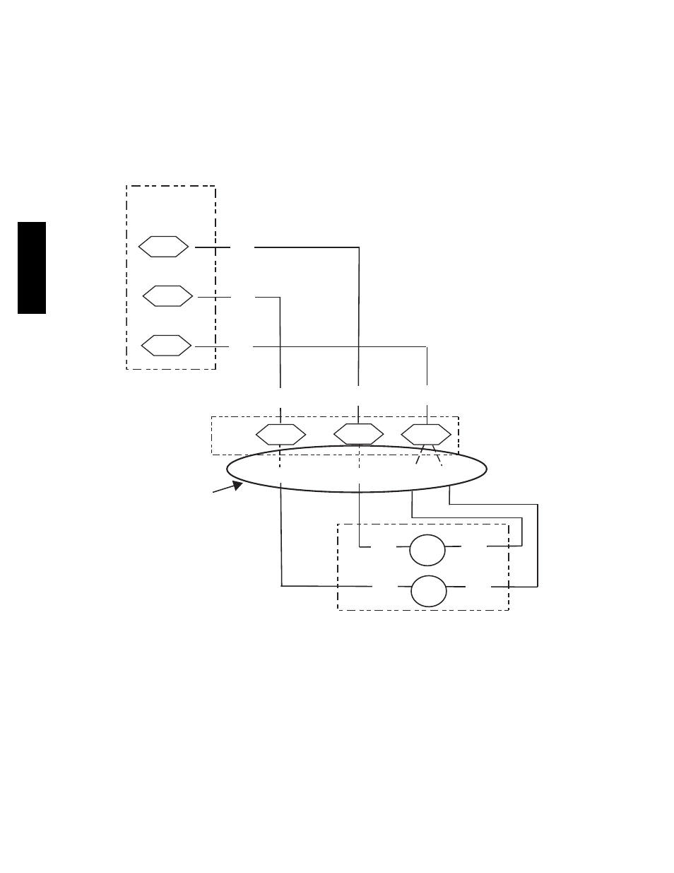
Heater Low--Voltage Control Connections —
One or two heaters can be installed in the unit. Use the
wiring procedure listed below for each heater as
determined by the number of stages in the heater.
Single Stage Heaters: Single--stage heaters will have an
orange and a brown control wire. Connect these to the
orange and brown wires located on TB4.
Two Stage Heaters: Two--stage heaters will have orange,
purple, red and brown wires. The orange and the purple are
the control wires and the red and brown wires feed the
safety circuit. Connect both the orange and the purple wires
to the orange wire locations of TB4. Connect the red and
brown wires to red and brown wires on TB4. If more than
one heater is installed, repeat the wiring procedure for the
second heater. The 3 locations across the top of TB4 do
allow a switch to be installed in series with some of the
heaters in order to add additional heater control.
LCTB
CONTL
BOARD
ORN
BRN
Field
Connections
HR1: On Heater 1 in Position #1
HR2: On Heater 2 in Position #2 (if installed)
2
3
12
1
3
VIO
ORN
VIO
BRN
VIO
BRN BRN
VIO
2
TB4
VIO
HR2
HR1
BRN
VIO
BRN
Elec Htr
C08331
Fig. 34 -- Accessory Electric Heater Control Connections
50TC
--
*16