Caution, Electric heaters – Carrier 50TC User Manual
Page 17
17
HEATER
MOUNTING
BRACKET
HEATER
MODULE
(LOCATION 2)
HEATER
MODULE
(LOCATION 1)
SINGLE POINT
BOX
MOUNTING
SCREW
SINGLE
POINT BOX
HEATER
COVERS
MANUAL RESET
LIMIT SWITCH
DISCONNECT
MOUNTING
LOCATION
C10029
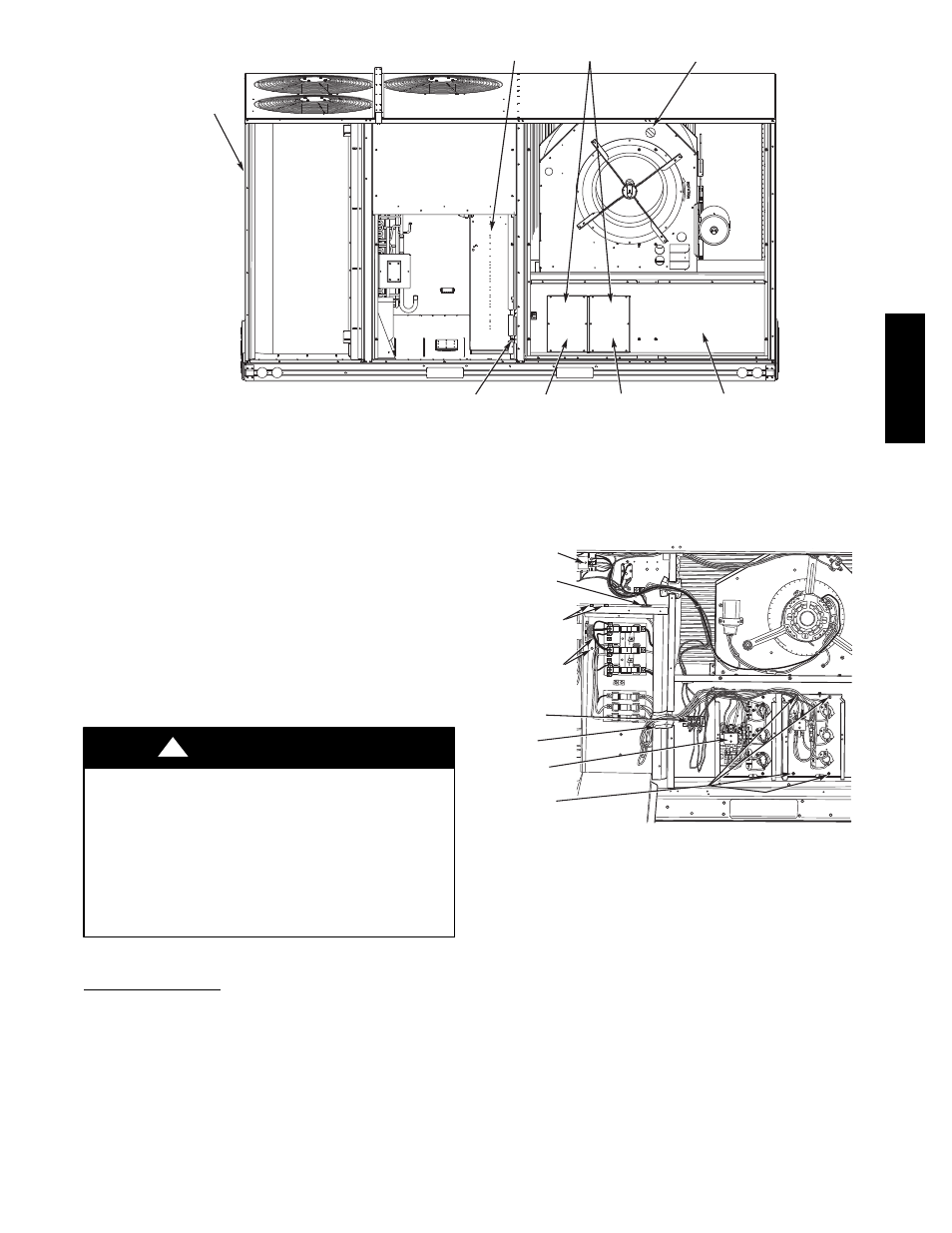
Fig. 32 -- Typical Component Location
Heat Anticipator Settings —
Set heat anticipator settings at 0.14 amp for the first stage
and 0.14 amp for second--stage heating, when available.
Electric Heaters
50TC--D16 units may be equipped with field--installed
accessory electric heaters. The heaters are modular in design.
One or two heater modules may be used in a unit.
Heater modules are installed in the compartment below the
indoor (supply) fan outlet. Access is through the indoor
access panel. Heater modules slide into the compartment on
tracks along the bottom of the heater opening. See Fig. 32.
UNIT DAMAGE HAZARD
Failure to follow this caution may result in equipment
damage.
Not all available heater modules and single point
boxes may be used in every unit. Use only those
heater modules that are UL listed for use in a specific
size unit. Refer to the label on the unit cabinet for the
list of approved heaters and single point boxes.
CAUTION
!
Single Point Boxes
When heaters are installed, power wiring to both heaters
and the rest of the unit is connected via the single point
box accessory, which will be installed directly under the
unit control box, just to the left of the partition separating
the indoor section (with electric heaters) from the outdoor
section. The single point box has a hinged access cover.
See Fig. 33. The single point box also includes tap
conductors to complete the wiring between the single
point box and the unit’s main control box terminals. Refer
to the accessory heater and Single Point Box installation
instructions for details on tap connections.
ALLIED PA
MODEL NO.
ERIAL NO.
CORP.
11
13
21
23
OD
22.2
3
1
23
ISTED AIR
NDITIONING
UIP ACCESS
346N.
P / N
2-
5610-4
REV
1
1
13
2
1
2
3
CONTROL
BOX
BUSHING
SINGLE
POINT BOX
MOUNTING
SCREWS
FOAM
BUSHING
DRIP BOOT
BRACKET
MOUNTING
SCREWS
HEATER
RELAYS
POWER
WIRES
HEATER
MOUNTING
SCREWS
C08136
Fig. 33 -- Typical Single Point Installation
Heater and Supplementary Fuses —
When the unit MOCP device value exceeds 60--A,
unit--mounted supplementary fuses are required for each
heater circuit. These fuses are included in accessory
Single Point Boxes, with power distribution and fuse
blocks.
All fuses on 50TC--*16 units are 60--A. (Note that all
heaters are qualified for use with a 60--A fuse, regardless
of actual heater ampacity, so only 60--A fuses are
necessary.)
50TC
--
*16