Warning, Step 9 — install external condensate trap and line, Step 10 — make electrical connections – Carrier 50TC User Manual
Page 11
11
Step 9 — Install External Condensate Trap and
Line
The unit has one
3
/
4
-in. condensate drain connection on
the end of the condensate pan and an alternate connection
on the bottom. See Fig. 15. Unit airflow configuration
does not determine which drain connection to use. Either
drain connection can be used with vertical or horizontal
applications.
When using the standard side drain connection, ensure the
red plug in the alternate bottom connection is tight. Do
this before setting the unit in place. The red drain pan can
be tightened with a
1
/
2
--in. square socket drive extension.
To use the alternate bottom drain connection, remove the
red drain plug from the bottom connection (use a
1
/
2
--in.
square socket drive extension) and install it in the side
drain connection.
DRAIN
(FACTORY-INSTALLED)
PLUG
CONDENSATE PAN (SIDE VIEW)
STANDARD
SIDE DRAIN
ALTERNATE
BOTTOM DRAIN
C08021
Fig. 15 -- Condensate Drain Pan (Side View)
The piping for the condensate drain and external trap can
be completed after the unit is in place. See Fig. 16.
NOTE: Trap should be deep enough to offset maximum unit static
difference. A 4” (102) trap is recommended
.
MINIMUM PITCH
1” (25mm) PER
10’ (3m) OF LINE
BASE RAIL
OPEN
VENT
TO ROOF
DRAIN
DRAIN PLUG
ROOF
CURB
SEE NOTE
2˝ (51) MIN
C08022
Fig. 16 -- Condensate Drain Piping Details
All units must have an external trap for condensate
drainage. Install a trap at least 4-in. (102 mm) deep and
protect against freeze-up. If drain line is installed
downstream from the external trap, pitch the line away
from the unit at 1-in. per 10 ft (25 mm in 3 m) of run. Do
not use a pipe size smaller than the unit connection
(
3
/
4
-in.).
Step 10 — Make Electrical Connections
ELECTRICAL SHOCK HAZARD
Failure to follow this warning could result in personal
injury or death.
Unit cabinet must have an uninterrupted, unbroken
electrical ground to minimize the possibility of personal
injury if an electrical fault should occur. This ground may
consist of electrical wire connected to unit ground lug in
control compartment, or conduit approved for electrical
ground when installed in accordance with NEC (National
Electrical Code); ANSI/NFPA 70, latest edition (in
Canada, Canadian Electrical Code CSA [Canadian
Standards Association] C22.1), and local electrical codes.
!
WARNING
NOTE: Field--supplied wiring shall conform with the
limitations of minimum 63_F (33_C) rise.
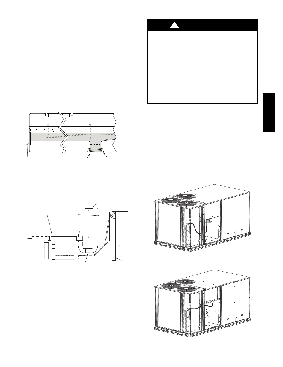
Field Power Supply —
For those units without through--the--curb power, conduit
must be used to route the main power from the condenser
end, via the power entry in the corner post of the unit (see
Figs. 17, 18 and 19) to either the factory option disconnect
or the bottom of the control box. 1” conduit is provided
wrapped around compressor. A second conduit is provided
with factory installed powered convenience outlet. For those
units that require conduit larger than 1”, it must be field
supplied. Figs. 17, 18 and 19 show the various wire routings.
C10010
Fig. 17 -- Conduit into Factory Option Disconnect
C10011
Fig. 18 -- Conduit into Control Box
50TC
--
*16