Warning – Carrier 50TC User Manual
Page 15
15
ELECTRICAL OPERATION HAZARD
Failure to follow this warning could result in personal
injury or death.
Using unit--mounted convenience outlets: Units with
unit--mounded convenience outlet circuits will often
require that two disconnects be opened to de--energize
all power to the unit. Treat all units as electrically
energized until the convenience outlet power is also
checked and de--energization is confirmed. Observe
National Electrical Code Article 210, Branch Circuits,
for use of convenience outlets.
!
WARNING
Installing Weatherproof Cover: A weatherproof
while-in-use cover for the factory-installed convenience
outlets is now required by UL standards. This cover
cannot be factory-mounted due its depth; it must be
installed at unit installation. For shipment, the
convenience outlet is covered with a blank cover plate.
The weatherproof cover kit is shipped in the unit’s control
box. The kit includes the hinged cover, a backing plate
and gasket.
DISCONNECT
ALL
POWER
TO
UNIT
AND
CONVENIENCE OUTLET. LOCK--OUT AND TAG--OUT
ALL POWER.
Remove the blank cover plate at the convenience outlet;
discard the blank cover.
Loosen the two screws at the GFCI duplex outlet, until
approximately
1
/
2
-in (13 mm) under screw heads are
exposed. Press the gasket over the screw heads. Slip the
backing plate over the screw heads at the keyhole slots
and align with the gasket; tighten the two screws until
snug (do not over-tighten).
Mount the weatherproof cover to the backing plate as
shown in Fig. 27. Remove two slot fillers in the bottom of
the cover to permit service tool cords to exit the cover.
Check for full closing and latching.
RECEPTACLE
NOT INCLUDED
COVER – WHILE-IN-USE
WEATHERPROOF
BASE PLATE FOR
GFCI RECEPTACLE
C09022
Fig. 27 -- Weatherproof Cover Installation
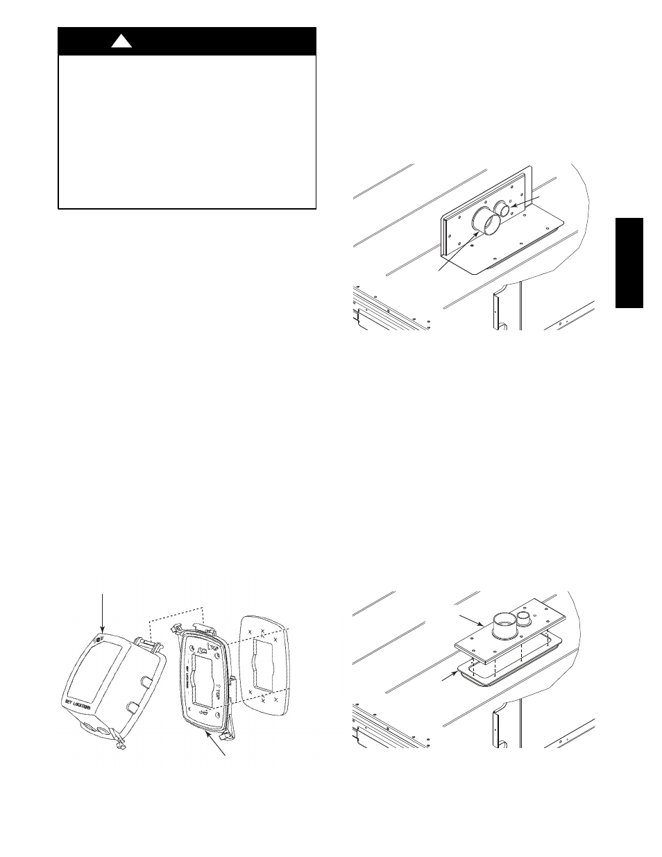
Factory--Option Thru--Base Connections —
This service connection kit consists of a
1
/
2
--in electrical
bulkhead connector and a 1
1
/
2
--in electrical bulkhead
connector, connected to an “L” bracket covering the
embossed (raised) section of the unit basepan in the
condenser section. See Fig. 28. The
1
/
2
--in bulkhead
connector enables the low--voltage control wires to pass
through the basepan. The 1
1
/
2
--in electrical bulkhead
connector allows the high--voltage power wires to pass
through the basepan.
1
/
2
” ELECTRICAL
BULKHEAD
CONNECTOR
1
1
/
2
” ELECTRICAL
BULKHEAD
CONNECTOR
C10907
Fig. 28 -- Thru--the--Base Option, Shipping Position
1. Remove the “L” bracket assembly from the unit.
2. Remove connector plate assembly from the “L”
bracket and discard the “L” bracket, but retain the
washer head screws and the gasket (located between
the “L” bracket and the connector plate assembly).
NOTE: Take care not to damage the gasket, as it is
reused in the following step.
3. Place the gasket over the embossed area in the
basepan, aligning the holes in the gasket to the holes
in the basepan. See Fig. 29.
4. Install the connector plate assembly to the basepan
using 8 of the washer head screws.
NOTE: If electrical connections are not going to occur at
this time, tape or otherwise cover the fittings so that
moisture does not get into the building or conduit in the
interim.
GASKET
CONNECTOR
PLATE
ASSEMBLY
C10908
Fig. 29 -- Installing Thru--the--Base Option
Check tightness of connector lock nuts before connecting
electrical conduits.
50TC
--
*16