Warning, Caution – Carrier 50TC User Manual
Page 7
7
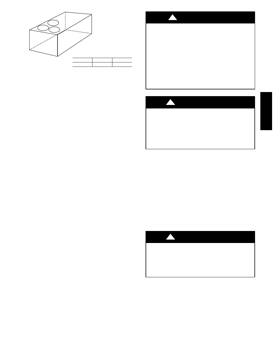
A-B
0.5” (13)
B-C
1.0” (25)
A-C
1.0” (25)
MAXIMUM ALLOWABLE
DIFFERENCE IN. (MM)
A
B
C
C10001
Fig. 4 -- Unit Leveling Tolerances
Step 5 — Field Fabricate Ductwork
Cabinet return-air static pressure (a negative condition)
shall not exceed 0.35 in. wg (87 Pa) with economizer or
0.45 in. wg (112 Pa) without economizer.
For vertical ducted applications, secure all ducts to roof curb
and building structure. Do not connect ductwork to unit.
Fabricate supply ductwork so that the cross sectional
dimensions are equal to or greater than the unit supply
duct opening dimensions for the first 18 in. (458 mm) of
duct length from the unit basepan.
Insulate and weatherproof all external ductwork, joints,
and roof openings with counter flashing and mastic in
accordance with applicable codes.
Ducts passing through unconditioned spaces must be
insulated and covered with a vapor barrier.
If a plenum return is used on a vertical unit, the return
should be ducted through the roof deck to comply with
applicable fire codes.
For Units with Accessory Electric Heaters —
All installations require a minimum clearance to
combustible surfaces of 1--in (25 mm) from duct for first
12--in (305 mm) away from unit.
Outlet grilles must not lie directly below unit discharge.
NOTE: A 90--degree elbow must be provided in the
ductwork to comply with UL (Underwriters Laboratories)
code for use with electric heat.
PERSONAL INJURY HAZARD
Failure to follow this warning could cause personal
injury.
For vertical supply and return units, tools or parts could
drop into ductwork and cause an injury. Install a
90--degree turn in the return ductwork between the unit
and the conditioned space. If a 90--degree elbow cannot
be installed, then a grille of sufficient strength and
density should be installed to prevent objects from
falling into the conditioned space. Due to electric
heater, supply duct will require 90--degree elbow.
!
WARNING
PROPERTY DAMAGE HAZARD
Failure to follow this caution may result in damage
to roofing materials.
Membrane roofs can be cut by sharp sheet metal
edges. Be careful when placing any sheet metal parts
on such roof.
CAUTION
!
Step 6 — Rig and Place Unit
When the unit is ready to be rigged and no longer will be
lifted by a fork truck, the wood protector under the basepan
must be removed. Remove 4 screws from each base rail.
Wood protector will drop to the ground. See instructions on
the unit base rails.
Keep unit upright and do not drop. Spreader bars are
required. Rollers may be used to move unit across a roof.
Level by using unit frame as a reference. See Table 1 and
Fig. 5 for additional information.
Lifting holes are provided in base rails as shown in Fig. 5.
Refer to rigging instructions on unit.
UNIT DAMAGE HAZARD
Failure to follow this caution may result in
equipment damage.
All panels must be in place when rigging. Unit is not
designed for handling by fork truck.
CAUTION
!
Before setting the unit onto the curb, recheck gasketing on
curb.
50TC
--
*16