Notice/avis – Carrier 50TC User Manual
Page 14
14
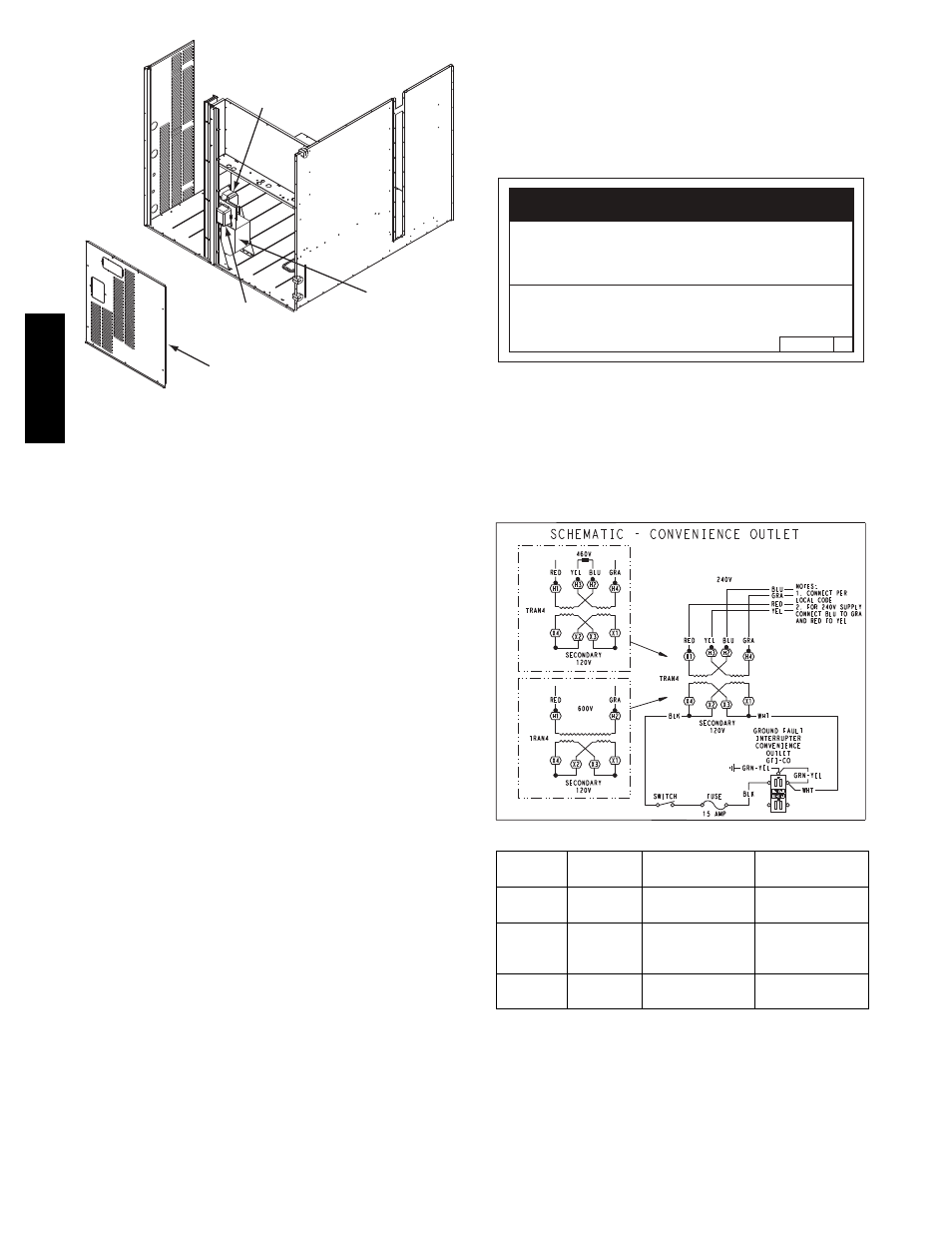
Convenience
Outlet
GFCI
Pwd-CO
Fuse
Switch
Pwd-CO
Transformer
Disconnect
Access Panel
C10857
Fig. 24 -- Convenience Outlet Location
Non--powered type: This type requires the field
installation of a general--purpose 125--volt 15--A circuit
powered from a source elsewhere in the building. Observe
national and local codes when selecting wire size and
conduit requirements, fuse or breaker requirements and
disconnect switch size and location. Route 125--v power
supply conductors into the bottom of the utility box
containing the duplex receptacle.
Unit--powered type: A unit--mounted transformer is
factory--installed to stepdown the main power supply
voltage to the unit to 115--v at the duplex receptacle. This
option also includes a manual switch with fuse, located in
a utility box and mounted on a bracket behind the
convenience outlet; access is through the panel beneath
the control box. See Fig. 24.
The primary leads to the convenience outlet transformer
are not factory--connected. Selection of primary power
source is a customer--option. If local codes permit, the
transformer primary leads can be connected at the
line--side terminals on the unit--mounted non--fused
disconnect switch; this will provide service power to the
unit when the unit disconnect switch is open. Other
connection methods will result in the convenience outlet
circuit being de--energized when the unit disconnect
switch is open. See Fig. 26. On a unit without a
unit--mounted disconnect, connect the source leads to the
main terminal block (TB1).
If the convenience outlet transformer is connected to the
line side of a field disconnect, the conduit provided with
the unit must be used to protect the wire as they are routed
from the transformer to the field disconnect. The end of
the conduit with the straight connector attaches to the
field disconnect. The other end does not need to connect
to the transformer; however, the conduit must be routed so
that all wiring is either in the conduit or behind the access
panel.
If the convenience outlet transformer is connected to the
line side of the factory disconnect option, route the wires
through the web bushing located on the bottom of the
disconnect box. For the load side wiring to the factory
option disconnect, route the wires through the hole on the
right side of the disconnect. Be sure to create a drip loop
at least 6” long.
2.0
50HE501288
NOTICE/AVIS
Convenience Outlet Utilization
Maximum Intermittent Use 15 - Amps
Maximum Continuous Use 8 - Amps
Observe a 50% limit on the circuit
Loading above 8 - Amps
Utilisation de la prise utilitaire
Usage intermittent maximum 15 - Amps
Usage continu maximum 8 - Amps
Observez une limite de 50% sur le circuit
Chargement au-dessus de 8 - Amps
C10077
Fig. 25 -- Convenience Outlet Utilization Notice
Test the GFCI receptacle by pressing the TEST button on
the face of the receptacle to trip and open the receptacle.
Check for proper grounding wires and power line phasing
if the GFCI receptacle does not trip as required. Press the
RESET button to clear the tripped condition.
C08283
UNIT
VOLTAGE
CONNECT
AS
PRIMARY
CONNECTIONS
TRANSFORMER
TERMINALS
208,
230
240
L1: RED +YEL
L2: BLU + GRA
H1 + H3
H2 + H4
460
480
L1: RED
Splice BLU + YEL
L2: GRA
H1
H2 + H3
H4
575
600
L1: RED
L2: GRA
H1
H2
Fig. 26 -- Unit Powered Convenience Outlet Wiring
Fuse on power type: The factory fuse is a Bussman
“Fusetron” T--15, non--renewable screw--in (Edison base)
type plug fuse.
50TC
--
*16