Warning – Carrier 50TC User Manual
Page 12
12
C10012
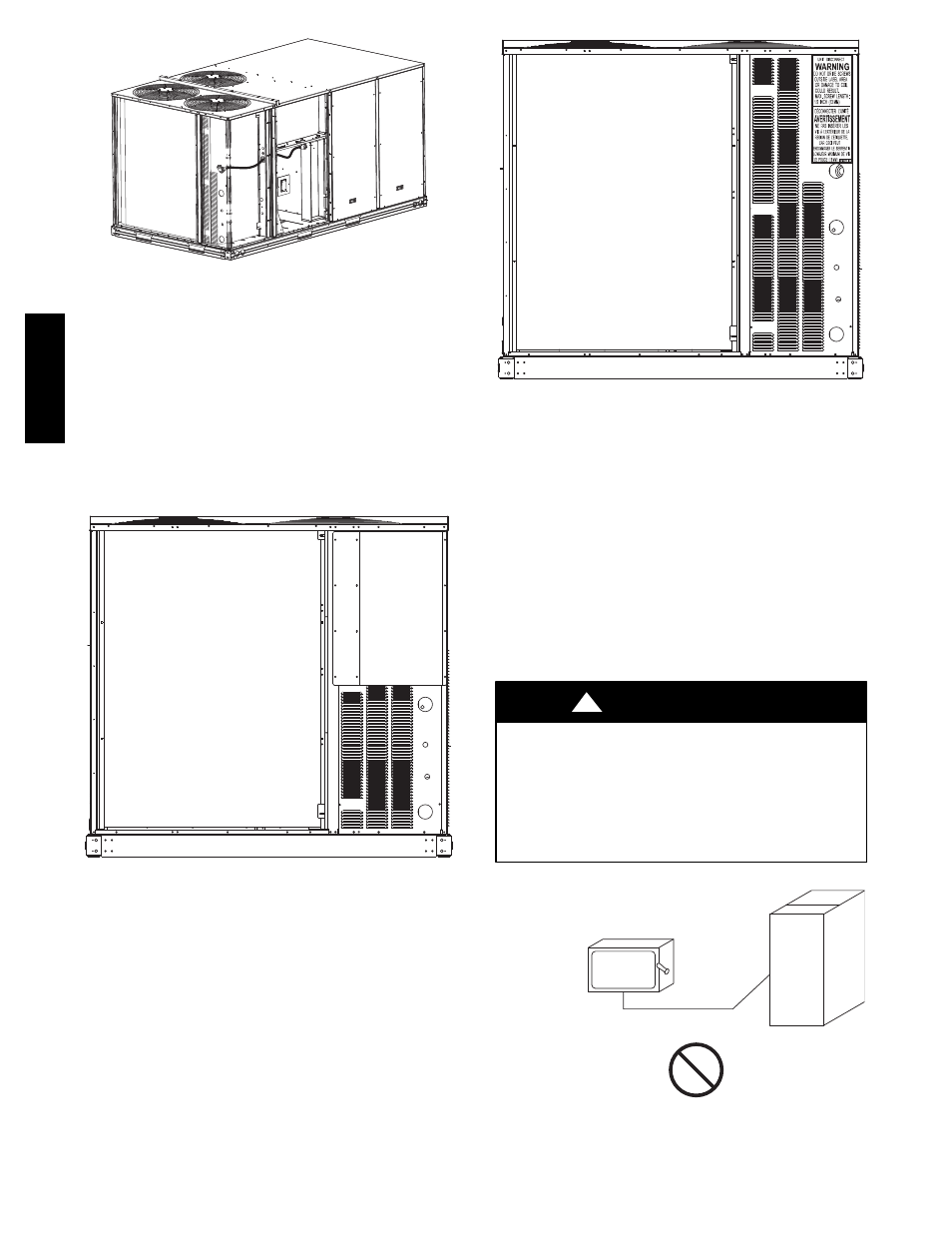
Fig. 19 -- Conduit into Single Point Box
If the field disconnect is larger than 100A, it must be
attached to the unit using accessory CRDISBKT001A00
— disconnect switch bracket — (see Fig. 20). Follow the
instructions provided with this accessory. For smaller field
disconnects, be sure to use
1
/
2
” screws to mount the
disconnect directly to the end panel, following the
instructions on the Field Disconnect Warning label (see
Fig. 21). In either case, set the disconnect vertical location
on the unit so that a 90_ fitting can be used to connect the
conduit to the disconnect.
C10853
Fig. 20 -- Mounting Position for Field Disconnects
(over 100A)
C10854
Fig. 21 -- Mounting Position for Field Disconnects
(up to 100A)
Field power wires are connected to the unit at line--side
pressure lugs at the main terminal block (TB1) or at
factory--installed option non--fused disconnect switch.
Max wire size is #2 AWG (copper only). (See Fig. 23)
NOTE: TEST LEADS -- Unit may be equipped with
short leads (pigtails) on the field line connection points off
the optional disconnect switch. These leads are for factory
run--test purposes only; remove and discard before
connecting field power wires to unit connection points.
Make field power connections directly to line connection
pressure lugs only.
FIRE HAZARD
Failure to follow this warning could result in
intermittent operation or performance satisfaction.
Do not connect aluminum wire between disconnect
switch and air conditioning unit. Use only copper
wire. (See Fig. 22.)
!
WARNING
COPPER
WIRE ONLY
ELECTRIC
DISCONNECT
SWITCH
ALUMINUM
WIRE
A93033
Fig. 22 -- Disconnect Switch and Unit
50TC
--
*16