Operation, Maintenance, Nameplate – Qmark CWH3000 Series - Commercial Fan-Forced Wall Heaters User Manual
Page 4: Caution, Wiring diagrams (conʼt), Cwh3408b
Operation
1. Rotate the thermostat knob fully clockwise. This should
energize the heating elements and fan causing warm air to
flow from the hot air discharge at the openings in the
bottom of the grille.
2. After the operation check, rotate the thermostat knob to
the desired position to obtain room comfort.
3. For continuous fan-only operation (elements will not be
energized) rotate thermostat knob where indicator dot on
knob is aligned with FAN.
4. There will be a short delay from the time the unit is turned
on until the fan engages. This is to allow the elements time
to warm up. The fan will also continue to run once the unit
is turned off to allow the elements time to cool.
NOTE: For best results, the heater should be left “ON” constant-
ly during the heating season because the thermostat, when prop-
erly set, will maintain the desired temperature.
Maintenance
TO RESET MANUAL RESET LIMIT
Your heater is equipped with a manual reset safety thermal limit
control that will automatically turn the heater off to prevent a fire if
the heater overheats. This control is located on the fan panel
assembly between the element and fan blade and marked “reset”.
The red reset button can be seen through the front grille when the
heater is installed. To reset, allow the heater to cool, then push the
red button that is visible through the hole in the fan panel. The
heater should immediately return to normal operation.
Once each year the heater should be cleaned to remove dust and
other foreign material which has collected during the heating sea-
son. This is a simple operation when performed as follows:
1. Turn off the electric power at main line switch (or remove all
fuses) to disconnect electric power from the heater.
THIS IS IMPORTANT.
2. Remove the grille (Figure 4) and turn the disconnect switch to
the OFF position.
3. With a vacuum cleaner nozzle or dust cloth, remove dust
and other foreign material.
4. After cleaning, turn disconnect switch to ON position and
reinstall the grille.
5. Turn on the main line switch (or replace fuses) to restore
power to the heater. The heater is now ready for another
season of operation.
OPERATION OF THE MANUAL RESET SAFETY THERMAL LIMIT CON-
TROL IS AN INDICATION THAT THE HEATER HAS BEEN SUBJECTED
TO SOME ABNORMAL CONDITION. IT IS RECOMMENDED THAT THE
HEATER BE CHECKED BY A REPUTABLE ELECTRICIAN OR REPAIR
SERVICE TO ENSURE THE HEATER HAS NOT BEEN DAMAGED.
DO NOT USE WATER OR DAMP CLOTH FOR CLEANING AND DO
NOT DISTURB THE HEATING ELEMENT.
MODEL NO.
CWH3408B
DATE CODE:
0402
FAN FORCED WALL HEATER
APPAREIL DE CHAUFFAGE MURAL À AIR PULSÉ
VOLTS AC
60HZ WATTS PHASE
208
4000 1
MUST BE USED WITH BACK BOX
DO NOT OPERATE WITHOUT FRONT COVER IN PLACE.
DOIT ÉTRE UTILISÉ AVEC BOÎTIER ARRIÈRE AWH-BB
NE PAS UTILISER SI LE COUVERCLE AVANT NʼEST PAS EN PLACE.
MARLEY ENGINEERED PRODUCTS
BENNETTSVILLE, SC 29512
4104-2046-058
7746 LISTED
ROOM HEATER
CAUTION
!
CAUTION
!
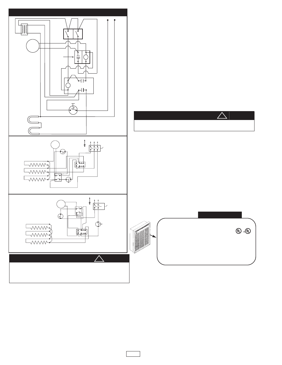
WIRING DIAGRAMS (Conʼt)
Transformer
Motor
Element
C
6
2
4
8
1
0
C
Manual
Reset
Heat
Thermostat
O
L1
L1
L2
L2/N
C
Time Delay
For Fan
Fan Only
Switch
To
Disconnect
Switch
P
R
I.
S
E
C.
1500/2000 WATT
HEATERS
347V, 600V
ELEMENTS
FAN
MOTOR
FAN
DELAY
RELAY
FIELD WIRING
GND
THERMOSTAT MANUAL
RESET
1
6
8
4
6
2
WIRING DIAGRAM
FOR THREE PHASE WALL HEATERS
CYC
L1
L2
OFF
DISCONNECT
ELEMENTS
FIELD WIRING
GND
WIRING DIAGRAM
4800 WATT 208 VOLT
SINGLE PHASE WALL HEATER
DISCONNECT
FAN
MOTOR
FAN
DELAY
MANUAL
RESET
RELAY
1
0
8
4
6
2
CYC
L1
L2
OFF
ELEMENTS
FAN
MOTOR
FAN
DELAY
RELAY
FIELD WIRING
GND
THERMOSTAT MANUAL
RESET
1
6
8
4
6
2
WIRING DIAGRAM
FOR THREE PHASE WALL HEATERS
CYC
L1
L2
OFF
DISCONNECT
ELEMENTS
FIELD WIRING
GND
WIRING DIAGRAM
4800 WATT 208 VOLT
SINGLE PHASE WALL HEATER
DISCONNECT
FAN
MOTOR
FAN
DELAY
MANUAL
RESET
RELAY
1
0
8
4
6
2
CYC
L1
L2
OFF
NAMEPLATE
THREE PHASE
WALL HEATERS
4800 WATT SINGLE
PHASE HEATERS
208V
Diagram 4
Diagram 5
Diagram 6
4